LightHouse v3.12 Advanced Operation instructions
Notices
Trademark and patents notice
Raymarine, Tacktick, Clear Pulse, Truzoom, SeaTalk, SeaTalkhs , SeaTalkng, and Micronet, are registered or claimed trademarks of Raymarine Belgium.
FLIR, DockSense, LightHouse, DownVision, SideVision, RealVision, HyperVision, Dragonfly, Element, Quantum, Axiom, Instalert, Infrared Everywhere, The World’s Sixth Sense and ClearCruise are registered or claimed trademarks of FLIR Systems, Inc.
All other trademarks, trade names, or company names referenced herein are used for identification only and are the property of their respective owners.
This product is protected by patents, design patents, patents pending, or design patents pending.
Fair Use Statement
You may print no more than three copies of this manual for your own use. You may not make any further copies or distribute or use the manual in any other way including without limitation exploiting the manual commercially or giving or selling copies to third parties.
Software updates

|
Check the Raymarine website for the latest software releases for your product. |
Product documentation

|
The latest versions of all English and translated documents are available to download in PDF format from the website: www.raymarine.com/manuals. Please check the website to ensure you have the latest documentation. |
Publication copyright
Copyright ©2020 Raymarine UK Ltd. All rights reserved.
Important information

|
Warning: Ensure safe navigation |
|
This product is intended only as an aid to navigation and must never be used in preference to sound navigational judgment. Only official government charts and notices to mariners contain all the current information needed for safe navigation, and the captain is responsible for their prudent use. It is the user’s responsibility to use official government charts, notices to mariners, caution and proper navigational skill when operating this or any other Raymarine product. |
|
|
Warning: Radar transmission safety |
|
The radar scanner transmits electromagnetic energy. Ensure all personnel are clear of the scanner when the radar is transmitting.
|
|
|
Warning: Sonar operation |
|
Disclaimers
Raymarine does not warrant that this product is error-free or that it is compatible with products manufactured by any person or entity other than Raymarine.
This product uses digital chart data, and electronic information from Global Navigation Satellite Systems (GNSS) which may contain errors. Raymarine does not warrant the accuracy of such information and you are advised that errors in such information may cause the product to malfunction. Raymarine is not responsible for damages or injuries caused by your use or inability to use the product, by the interaction of the product with products manufactured by others, or by errors in chart data or information utilized by the product and supplied by third parties.
This product supports electronic charts provided by third party suppliers which may be embedded or stored on memory card. Use of such charts is subject to the supplier’s End-User Licence Agreement.
Open source license agreements
This product is subject to certain open source license agreements. Copies of the license agreements can be found on the Raymarine website: www.raymarine.com/manuals/.
Warranty registration
To register your Raymarine product ownership, please visit www.raymarine.com and register online.
It is important that you register your product to receive full warranty benefits. Your unit package includes a bar code label indicating the serial number of the unit. You will need this serial number when registering your product online. You should retain the label for future reference.
Technical accuracy
To the best of our knowledge, the information in this document was correct at the time it was produced. However, Raymarine cannot accept liability for any inaccuracies or omissions it may contain. In addition, our policy of continuous product improvement may change specifications without notice. As a result, Raymarine cannot accept liability for any differences between the product and this document. Please check the Raymarine website (www.raymarine.com) to ensure you have the most up-to-date version(s) of the documentation for your product.
Document and product information
Product documentation
All documents are available to download in PDF format from the Raymarine website www.raymarine.com.
Applicable software version
Compatible MFDs
| Software version | Compatible MFDs |
|---|---|
|
LH3.12 |
|
|
LH3.11 LH3.10.71 LH3.10 LH3.9 LH3.8 LH3.7 LH3.6 LH3.5 |
|
|
LH3.4 LH3.3 |
|
|
LH3.2 |
|
|
LH3.1 |
|
|
LH3.0 |
|
LightHouse 3 support for eS Series and gS Series Multifunction displays
Systems that include eS Series and gS Series MFDs upgraded from LightHouse 2 to LightHouse 3 cannot be updated to LightHouse 3 version 3.12. To update Axiom MFDs to version 3.12 in these mixed MFD systems, you must remove the eS Series and gS Series MFDs from the same network as Axiom MFDs.
eS Series and gS Series MFDs remain compatible with LightHouse 3 versions 3.3 to 3.11.
New software features
- Ended compatibility with eS Series and gS series MFDs.
- Added support for new LightHouse Standard Charts and LightHouse Premium Charts.
- Added support for exFat MicroSD Card file system format.
- Added support for the new RayConnect mobile app.
- New display color themes and display modes.
- New fish detection feature.
- New AIS target names display option.
- New auto find ship option.
- New Audio sidebar
- Improved Find Nearest feature and Chart object information boxes in Chart app.
User manuals Print Shop
Printed manuals are ideal for keeping onboard your vessel, as a useful source of reference whenever you need assistance with your Raymarine product.
Visit http://www.raymarine.co.uk/view/?id=5175 to order a printed manual, delivered directly to your door.
For further information about the Print Shop, please visit the Print Shop FAQ pages: http://www.raymarine.co.uk/view/?id=5751.
Note:
|
General information
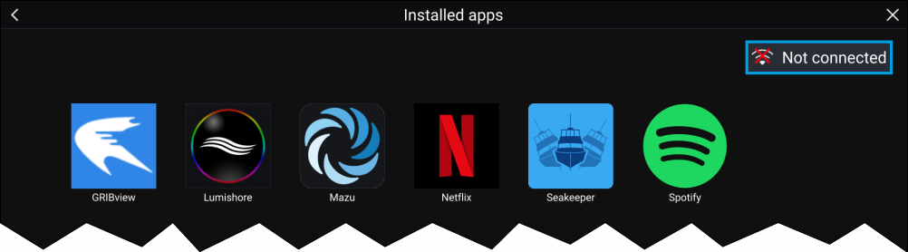
MFD and LightHouse third-party apps
Sidebar
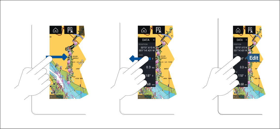
The Sidebar is displayed automatically in the Chart app when a Goto or follow is initiated. It can also be displayed at anytime by sliding your finger from left to right from the left edge of the screen. Swiping right to left will hide the Sidebar.
To customize the displayed data, press and hold on the Data item you want to change and select Edit from the pop-over options.
Customizing data sidebars
Switching sidebars
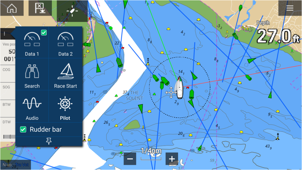
Data 1, Data 2 and Search sidebars are always available. The Race Start sidebar is available when a sailing vessel boat type is selected during the initial start up wizard. The Audio sidebar is available when compatible audio equipment is connected, and the Pilot sidebar is available when autopilot control is enabled.
Enable rudder bar
| Note: A rudder position sensor must be on the same network as your MFD for the Rudder bar to function. |
- No rudder data found.
- Rudder deflection to port.
- Rudder deflection to starboard.
Data overlays
Data overlays can be placed anywhere on the app page and can be placed over any app in a Splitscreen app page.
Data overlays can be customized from: .
In edit mode, drag the data overlay to the desired location. Touch and hold a Data overlay to display the pop-over menu, where you can Edit, Move, Resize or Delete the Data overlay.
Select Add to add another overlay or Done to exit edit mode.
Data overlay and Sidebar data items
|
Battery
|
Navigation
|
|
Boat
|
Pilot
|
|
Depth
|
Speed
|
|
Display
|
Time
|
|
Distance
|
Wind
|
|
Engine
|
Fuel (Gasoline)
|
|
Fuel
|
Fresh water
|
|
Environment
|
Grey water
|
|
GPS
|
Black water
|
|
Heading
|
Menus

|
The Main menu is displayed on the right side of the screen when the Menu icon is selected. |
|
Main menus Each MFD app includes a main menu. Main menus provide access to the MFD app’s features and settings, via menu options and menu pages. Selecting Back (<), Close (X) or selecting an area of the screen away from the menu, will close the menu. Selecting a menu item with a right arrow (>) will open a menu page or other menu options for that item. |
|
Menu pages Menu pages are accessed from main menu options and icons found on the Homescreen. Menu pages are fullscreen pages containing menu options and settings. Menu pages are usually set out in tabs with each tab containing options relevant to the tab’s title. Selecting tab titles will display the contents for that tab. Selecting Back (<) or Close will close the menu. |
|
Context menus Context menus are available in MFD apps. Context menus are accessed by selecting an object or location within the MFD app. Context menus provide context-sensitive information and options. Selecting more options will display further contextual menu options. Selecting Close (X) or selecting an area of the screen away from the menu, will close the menu. |
|
Pop-over menus Pop-over menus are available on the Homescreen, in MFD apps and from Menu pages. Pop-over options provide access to further menu options and settings. Selecting an area of the screen away from the menu will close the menu. |
Controls and settings

|
Toggle switch Toggle switches are used to enable (switch on) or disable (switch off) various features and settings. When enabled (switched on) the white circle will be moved right and the switch’s background will be filled Green. |

|
Page down Selecting will page down the current menu or page. When displayed you can also swipe the page to scroll up or down. |

|
Setting field Setting fields show the selected value for that control. Selecting a setting field will display the available options relevant to the options available. Depending on available options this could be in the following formats:
|

|
Setting button Setting buttons are available on Menu pages and Notification / Alarm messages to access further settings or confirm setting changes or changed MFD state. |
MFD app settings menu
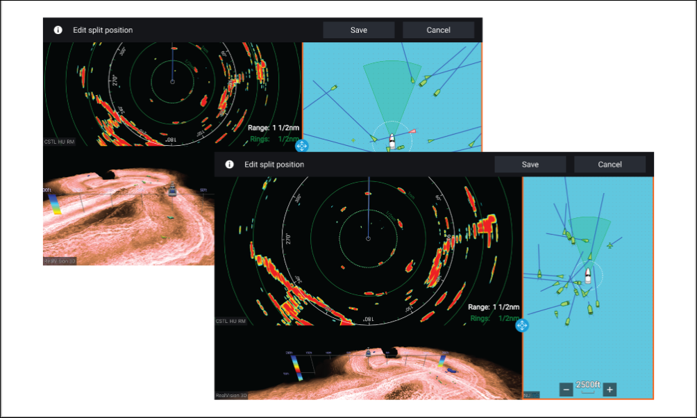
Editing the split ratio of a Splitscreen app page
Set up
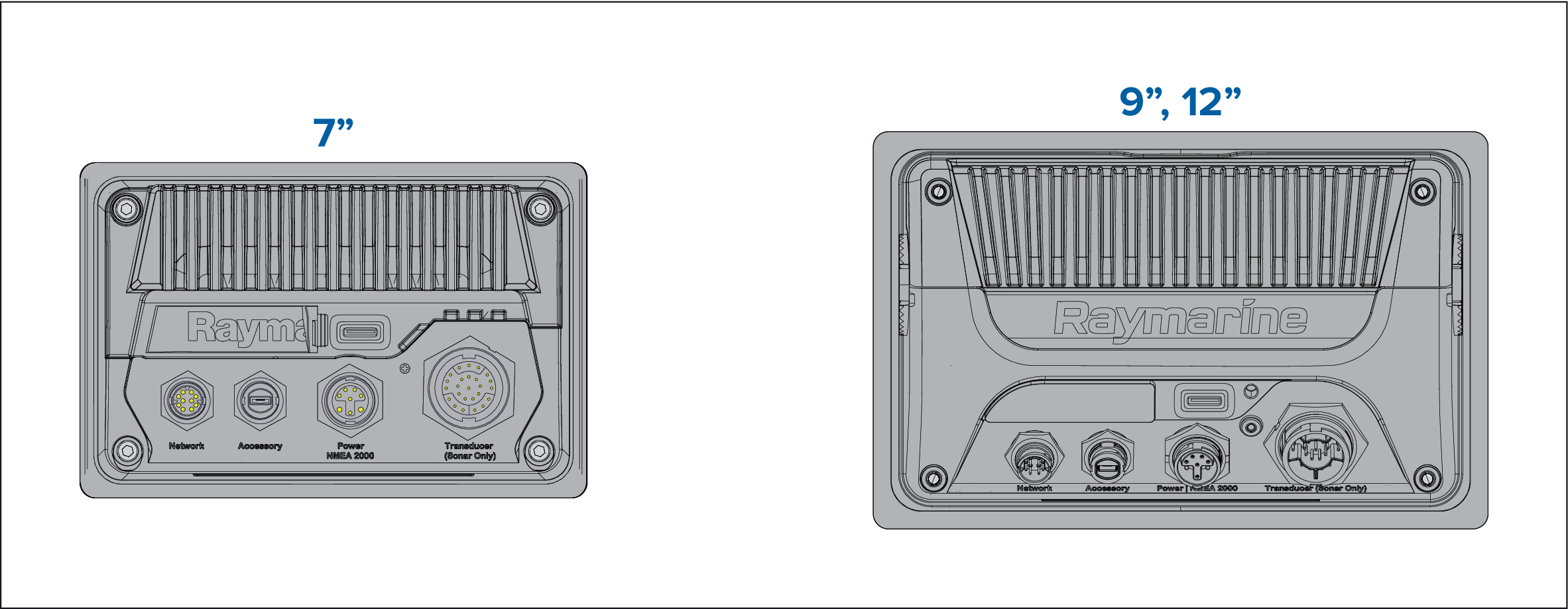
MFD physical buttons
Note:
|
Physical MFD buttons
|
Control |
Button |
Function |
|---|---|---|

|
Home |
Press to display the Homescreen. |

|
Menu |
Press to open or close menus. |

|
(1) User Programmable Button (UPB) |
You can select which function this button controls. Refer to Assigning a function to the User Programmable Button (UPB) for more information. |

|
Waypoint / MOB |
Press momentarily to place a waypoint at your vessel’s location. A long press activates the Man overboard (MOB) alarm. |

|
Power |
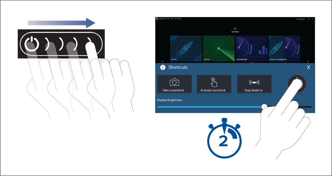
Press to power on the MFD. When the MFD is powered on, pressing this button displays the Shortcuts page. |

|
(2) Power swipe |
Swipe to power on the MFD. When the MFD is powered on, swipe again to display the Shortcuts page. |

|
Pilot |
Press momentarily to display or hide the Pilot sidebar. A long press engages the autopilot in locked heading mode, or disengages an active autopilot. |

|
Switch |
Press momentarily to switch the active pane in a splitscreen page. A long press expands the selected pane. |

|
Back |
Press to return to the previous menu or dialog. |

|
Range In |
Press to Range or Zoom In. |

|
Range Out |
Press to Range or Zoom Out. |

|
Uni-controller |
The Uni-controller consists of a center OK button, Directional controls and a Rotary knob. |
MFD Uni-controller
|
Control |
Control |
Function |
|---|---|---|

|
Ok |
Push the button to confirm a selection. |
|
Directional |
Use the 8-way directional controls to reposition the cursor onscreen. |
|
Rotary |
Turn clockwise to Range or Zoom In and counterclockwise to Range or Zoom out. |
Note:
|
Axiom and Axiom XL
Powering on the display

Powering off the display
|
Note:
When powered off, the unit may still draw a small amount of power from the battery. If this is a concern, unplug the power supply or switch off at the breaker. |
Switching on and off at the breaker
When the breaker is switched back on, or the cable is reconnected, the MFD will resume in the same power state that it was in when it was switched off.
Axiom Pro, eS Series and gS Series
Powering off the display

Alternatively you can press and hold the Power button for approximately 6 seconds to power off your display.
|
Note:
When powered off, the unit may still draw a small amount of power from the battery. If this is a concern, unplug the power supply or switch off at the breaker. |
Switching on and off at the breaker
When the breaker is switched back on, or the cable is reconnected, the MFD will resume in the same power state that it was in when it was switched off.
Getting started
First power up
The list below shows the actions that should be performed on your new MFD:
- Power on the display.
- Select your Data master (only required on networks with more than 1 MFD).
- Complete the Startup wizard (the wizard will not be shown if you are connecting to an existing system that has already been set up).
- Read and agree to the Limitations on Use disclaimer.
- Select/check your preferred Data sources, if required.
- Perform Engine identification, if required.
- Select/check Transducer settings, if required
First power up Data master selection
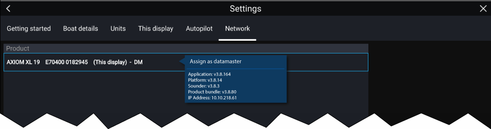
By default your MFD will be set as a Data master. If you are connecting to a network that already includes MFDs then on first power up you will be requested to confirm your Data master.
The “Multiple Data masters found” warning will be displayed whenever a new MFD is added to your network.
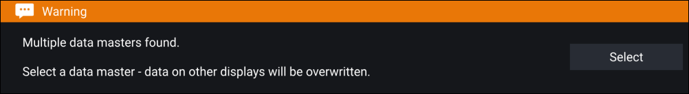
You can change your Data master at anytime by selecting Assign as Data master against a MFD listed in the Network tab of the Settings menu: .
Startup wizard
First power up Limitation on Use acknowledgement
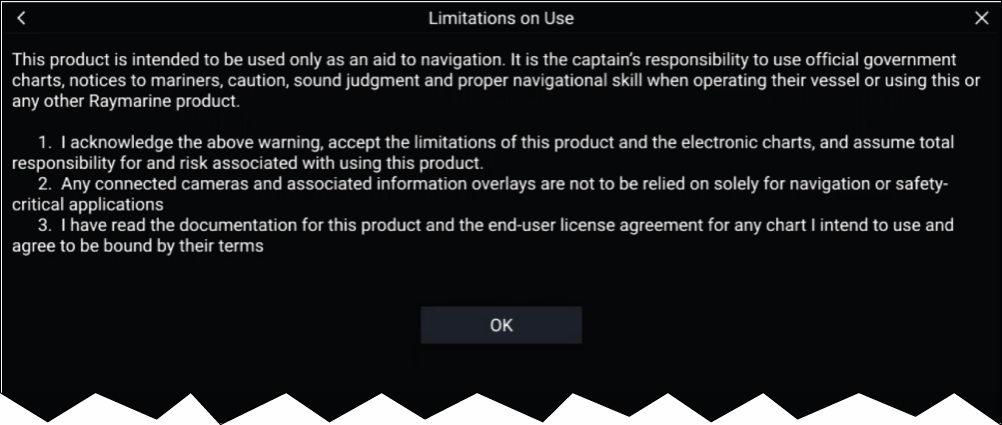
You must read and agree to the terms in order to use your MFD.
Selecting OK means you have accepted the terms of use.
Multiple data sources (MDS)
The following data types can have a preferred source assigned to them:
- GPS Position
- GPS Datum
- Time & Date
- Heading
- Depth
- Speed
- Wind
For MDS to be available on your system, all products in the system that use the data sources must be MDS-compliant. The system will report any products that are NOT MDS-compliant. It may be possible to upgrade the software for these non-compliant products, to make them compliant. Visit the Raymarine website (www.raymarine.com) to obtain the latest software for your products.
If MDS-compliant software is not available for the product and you do NOT want to use the system’s preferred data source, you must remove any non-compliant products from the system. You should then be able to select your preferred data source.
|
Note:
Once you have completed setting up your preferred data sources, you may be able to add non-compliant products back into the system. |
Data sources menu

Each tab enables you to view and select your preferred data source. The currently active data source will display its current value in use. Data source selection can be manual or set to automatic:
- Auto — your MFD will automatically select a device.
- Manual — you can manually select your preferred device.
Networked MFDs will automatically be updated to use the Data sources selected on your Data master MFD.
Identifying engines
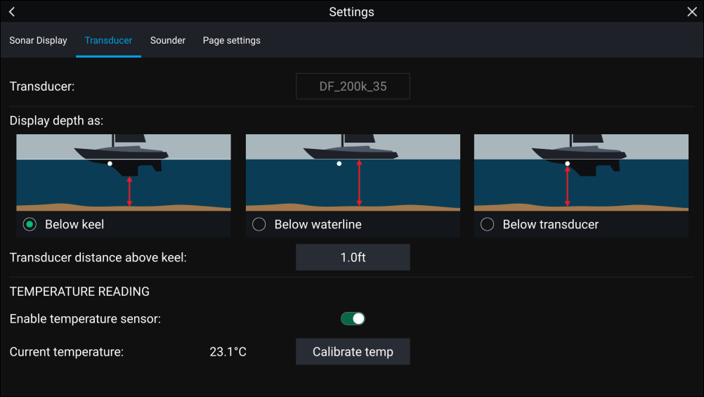
Configuring Transducer settings
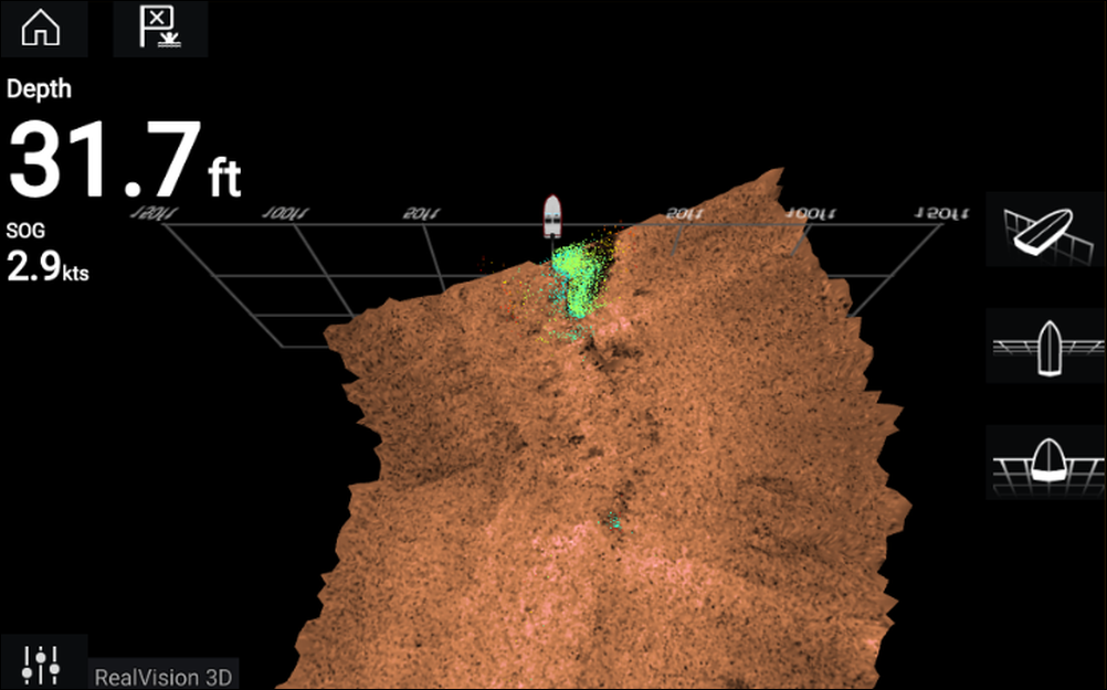
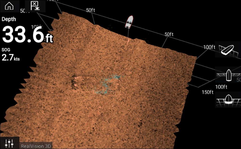
RealVision ™ 3D AHRS calibration
An uncalibrated transducer can produce an offset to the front edge of the render of the bottom in the sonar image, as illustrated below.
|
|
|
Uncalibrated |
Calibrated |
Calibration is an automatic process and starts after your vessel has turned approximately 100° at a speed of between 3 –15 knots. Calibration requires no user input, however at least a 270° turn is required before the calibration process can determine the local deviation and apply a relevant offset.
The time it takes to complete the calibration process will vary according to the characteristics of the vessel, the installation environment of the transducer, and the levels of magnetic interference at the time of conducting the process. Sources of significant magnetic interference may increase the time required to complete the calibration process. Certain areas with substantial magnetic deviation may require extra circles or “figure of 8” manoeuvres to be performed. Examples of such sources of magnetic interference include:
- Vessel engines
- Vessel alternators
- Marine pontoons
- Metal-hulled vessels
- Underwater cables
|
Note:
In some circumstances, it is beneficial to disable Realvision AHRS if local sources of magnetic interference are distorting the sonar image. Realvision AHRS can be disabled from Settings.
|
|
Note:
The Calibration process will require repeating after a Sonar reset or MFD Factory reset. |
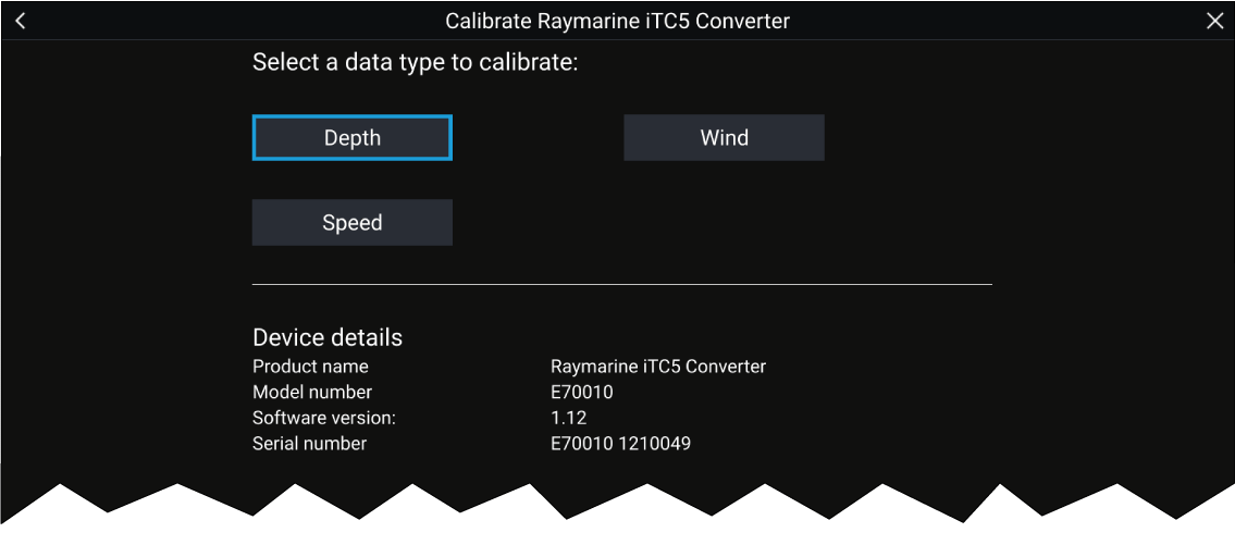
Transducer calibration (iTC-5)
|
Note:
Transducer calibration requirements:
|
|
Note:
You can only calibrate transducers that are directly connected to the iTC-5 instrument you select for calibration. In systems with more than 1 iTC-5, it is important to remember which transducer(s) are connected to each iTC-5 instrument. |
Network

Data selection
- Depth
- Wind
- Speed
Depth
|
Below keel |
Enter the distance between the transducer face and the bottom of the keel. |
|
Below waterline |
Enter the distance between the bottom of your keel and the waterline. |
|
Below transducer |
No offset required. |
Wind
|
Linearise transducer 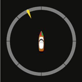
|
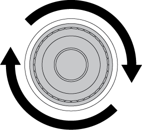
Turn your boat in a circle until all sectors have been calibrated (the ring turns green). |
|
Align wind transducer 
|
Head your boat directly into observed wind to align. |
|
Angle adjustment |
Apply an offset to the angle. |
|
Speed adjustment |
Apply a scaling factor to apparent wind speed. |
Speed
|
Note:
For best results, ensure that there is minimal or no tide/current effect when calibrating speed through water. |
|
Set STW to SOG |
Apply a scaling factor to all STW readings, based on the present difference between STW and SOG. |
|
Adjust STW |
Apply a scaling factor to all speed through water values. |
Assigning a function to the User Programmable Button (UPB)
Performing a settings or factory reset
Importing user data
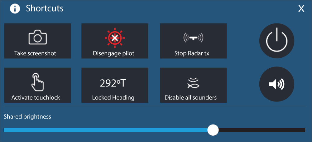
Shortcuts
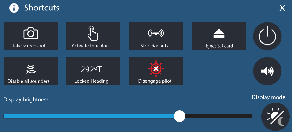
The following shortcuts are available:
Taking a screenshot
|
Note:
Due to protected content restrictions you cannot take a screenshot when the video input on an Axiom ™ Pro or the Video 2 or HDMI input on an Axiom ™ XL MFD is displayed onscreen. |
Activating touchlock
Radar standby
Eject SD card
Disabling all sounders
Autopilot shortcuts
Bluetooth volume control
Homescreen
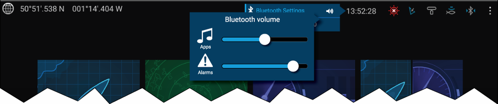
From the Homescreen select the Status area and then select the Speaker symbol to display the Bluetooth volume control for LightHouse ™ app and MFD alarms.
Shortcuts page

Press or swipe the Power button to display the Shortcuts page and then select the speaker symbol to display the Bluetooth volume control for LightHouse ™ apps and MFD alarms.
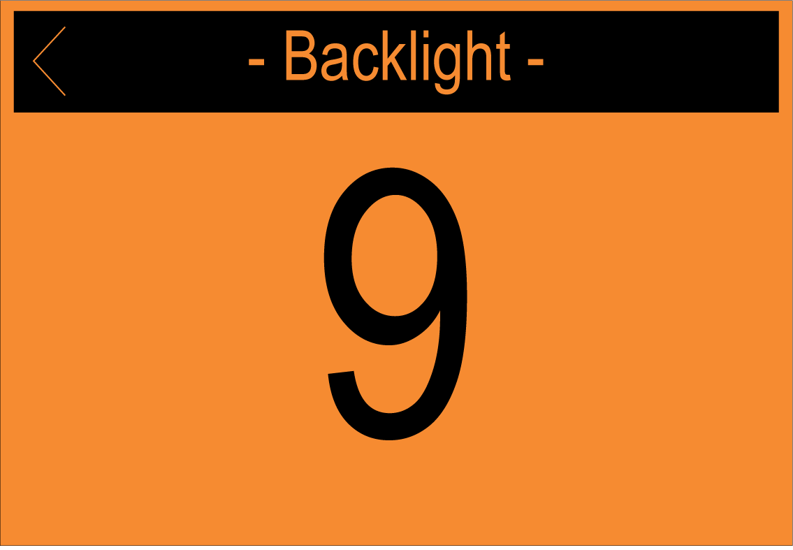
Adjusting brightness
Display mode
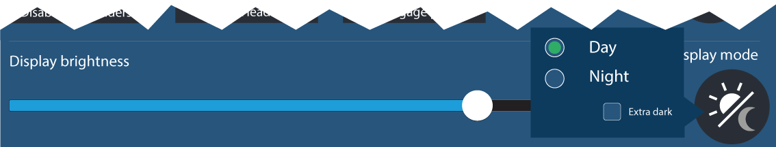
Press or swipe the Power button to display Shortcuts and then select the Display mode symbol to switch between Day, Night, and Extra dark display modes.
You can adjust the Display mode to suit the time of day:
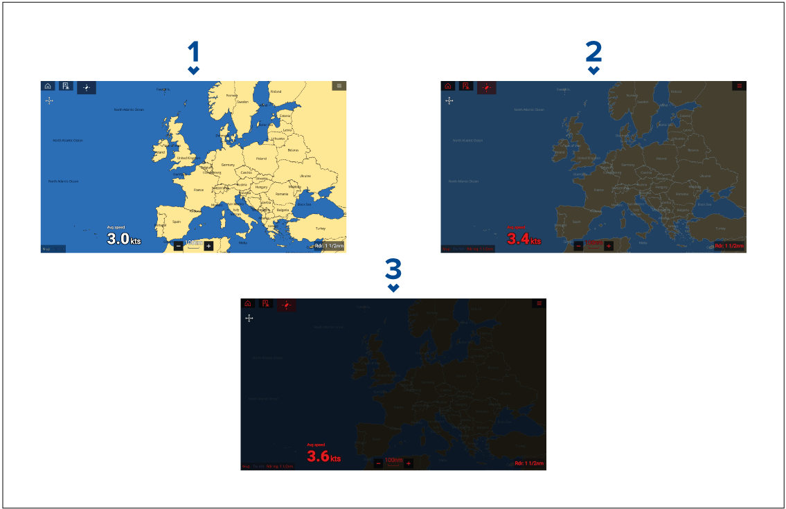
- Day — White user interface and a light background.
- Night — Red user interface and a dark background.
-
Extra dark — Red user interface and a very dark background.
Note: Night mode must be active before Extra dark can be selected.
Memory card compatibility
Compatible cards
The following types of MicroSD cards are compatible with your MFD:
|
Type |
Size |
Native card format | MFD supported Format |
|---|---|---|---|
|
MicroSDSC (Micro Secure Digital Standard Capacity) |
Up to 4GB |
FAT12, FAT16 or FAT16B |
NTFS, FAT32, exFAT |
|
MicroSDHC (Micro Secure Digital High Capacity) |
4GB to 32GB |
FAT32 |
NTFS, FAT32, exFAT |
|
MicroSDXC (Micro Secure Digital eXtended Capacity) |
32GB to 2TB |
exFAT |
NTFS, FAT32, exFAT |
- Speed class rating — For best performance it is recommended that you use Class 10 or UHS (Ultra High Speed) class memory cards, or better.
- Use branded memory cards — When archiving data it is recommended that you use good quality branded memory cards.
Caution: Care of chart and memory cards |
|
To avoid irreparable damage to and / or loss of data from chart and memory cards:
|
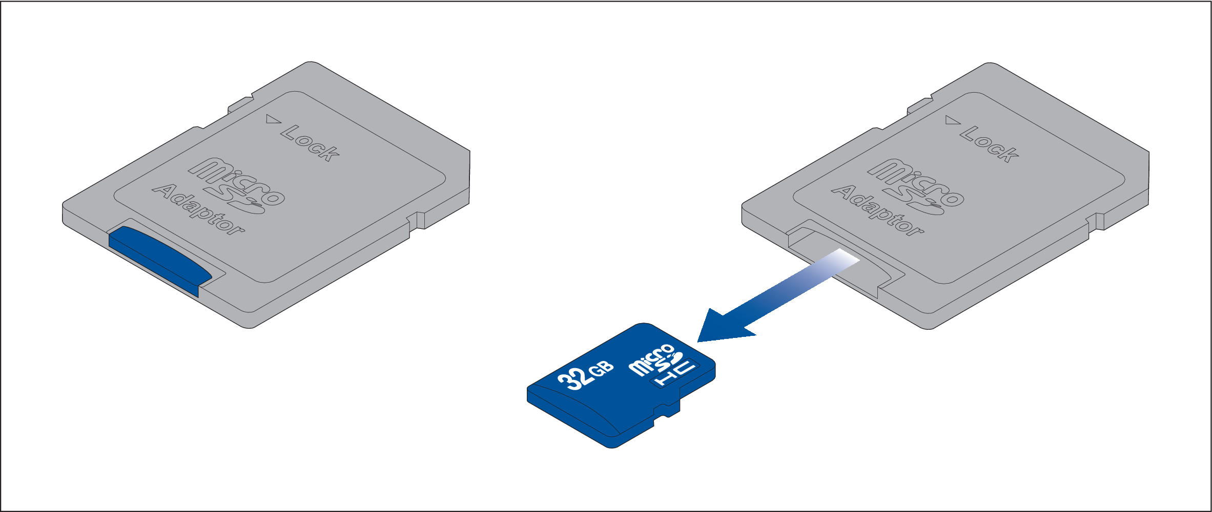
Removing MicroSD card from its adaptor
Inserting a MicroSD card — Axiom variants
Inserting a MicroSD card — Axiom Pro variants
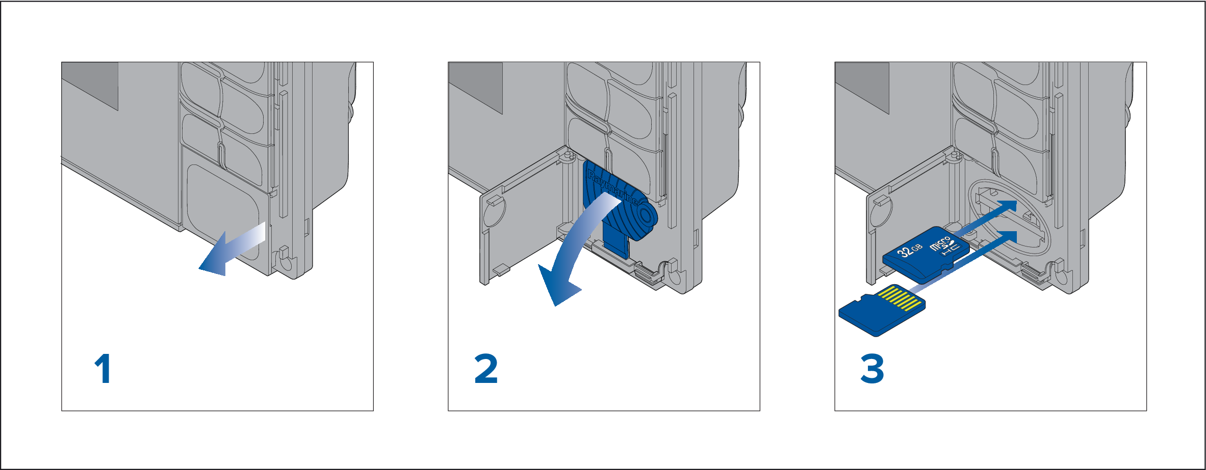
| Note: When inserting a card into the lower card slot the memory card must be orientated with the contacts pointing upwards. |
Inserting external storage devices - RCR
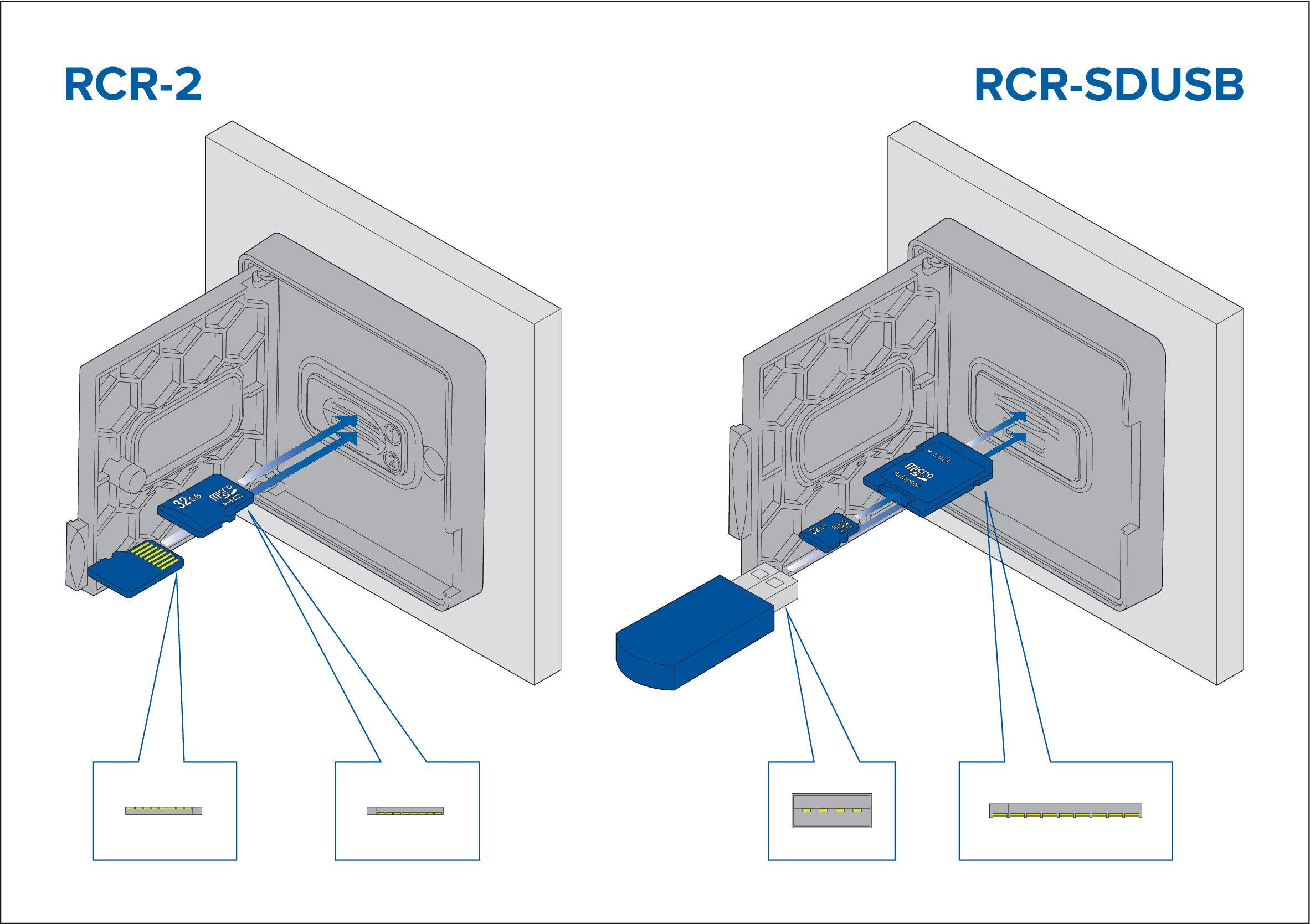
- RCR-SDUSB slot 1 — With the contacts facing down, insert an SD card (or an SD card adaptor containing a MicroSD card) into the upper slot, labelled (1), and push until it clicks into place.
- RCR-SDUSB slot 2 — With the contacts facing down, insert a USB drive directly into the lower slot, labelled (2).
- RCR-2 slot 1 — With the contacts facing down, insert a MicroSD card into the upper slot and push until it clicks into place.
- RCR-2 slot 2 — With the contacts facing up, insert a MicroSD card into the lower slot and push until it clicks into place.
Removing external storage (SD and MicroSD)
Caution: Ensure card reader cover or door is securely closed |
|
To prevent water ingress and consequent damage to the product, ensure that the card reader door or cover is firmly closed.
|
Software updates
Note:
|
Updating software using a memory card
Updating software via the internet
Device pairing
Pairing a RMK remote keypad
|
Note:
Please refer to the controls section of your keypad’s documentation for details on controlling MFDs using a keypad. |
Pairing with a Quantum Radar scanner
Pre-requisites:
- Ensure you have connected your Quantum Radar scanner in accordance with the instructions provided with the Radar scanner.
- Ensure you know your Radar scanner’s SSID and passcode.
Pairing a Bluetooth speaker
If pairing is successful the speaker will appear in the Paired devices list and display the Connected message.
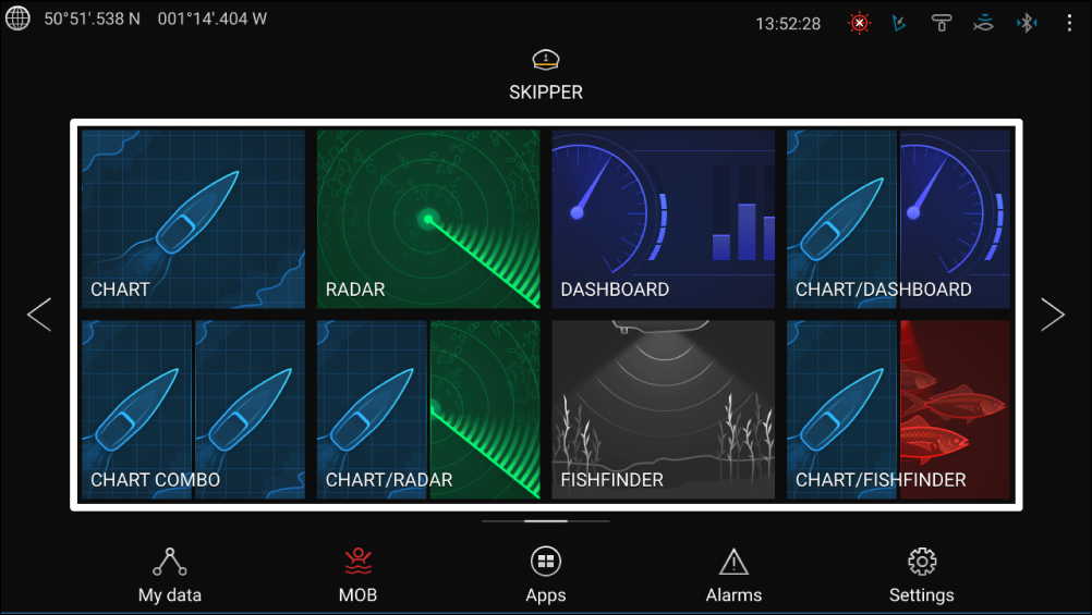
Homescreen
Accepting the Limitations on Use
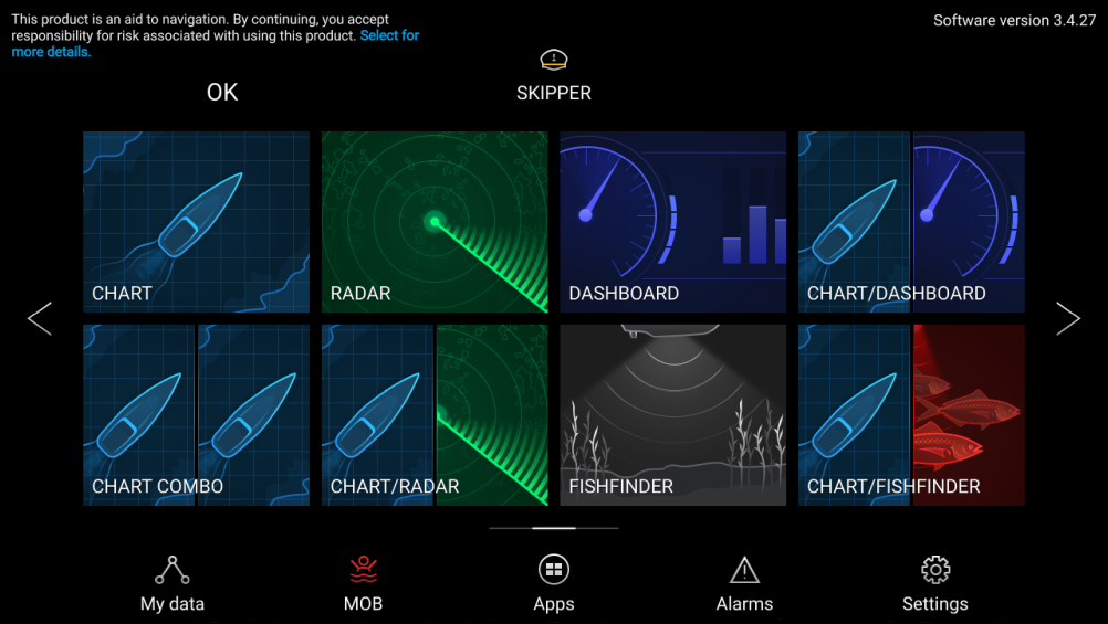
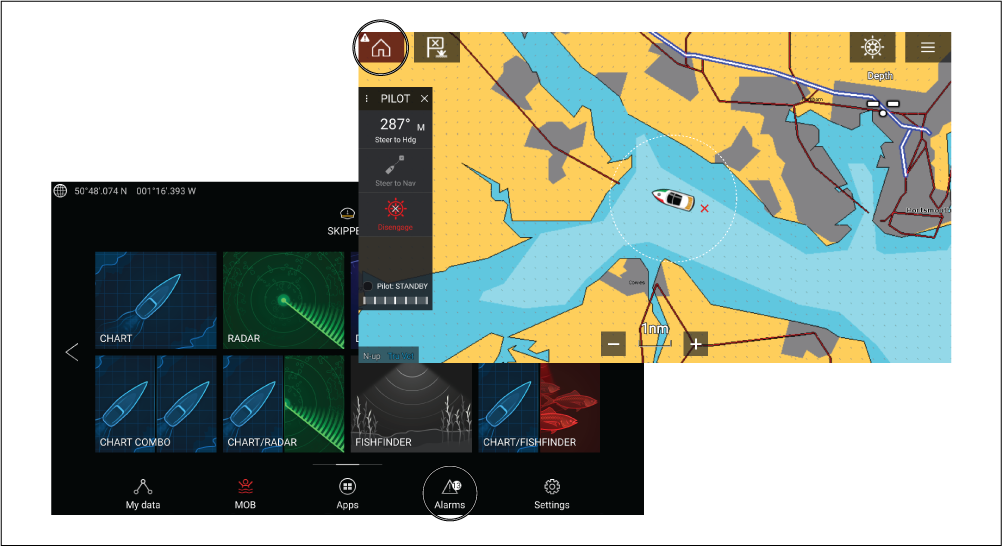
Homescreen overview

- GNSS position/fix details — Select the area to view fix accuracy and access GNSS settings.
- Profile — Select the area to change the profile in use or to create, edit or delete profiles.
- External devices and system time — Select this area to access Bluetooth settings, Disengage your autopilot or adjust the UTC time offset.
- App page icons — Select an icon to open the relevant MFD app page. Use the Left and Right arrows , or swipe your finger left or right across the area to cycle through the available Homescreen pages.
- Settings and data — This area provides access to the Settings, Alarms, Apps and My data menus. You can also activate the Man Over Board (MOB) alarm and disengage your autopilot.
|
Note:
When more than 1 display is connected to the same network, then the Homescreen of the MFD designated as Data Master will be mirrored on all MFDs. |
MFD Apps
MFD apps are displayed on your MFD in App pages. Each app page is accessed from the app page icons on the Homescreen. App pages can include more than 1 app. The available MFD apps are:
|
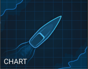
Chart — The Chart app displays electronic cartographic information from your Chart cards and when used in conjunction with a GNSS receiver, plots your vessel’s position. The Chart app can be used to mark specific locations using Waypoints, build and navigate Routes or keep a record of where you have been by recording a Track. For more information refer to Chart app |
|
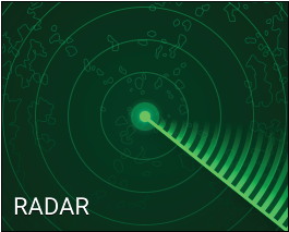
Radar — The Radar app is a situational awareness aid that displays a graphical representation of your surroundings in relation to your vessel using the echo/target returns from a connected Radar scanner. The Radar app allows you to track targets and measure distances and bearings For more information refer to Radar app |
|
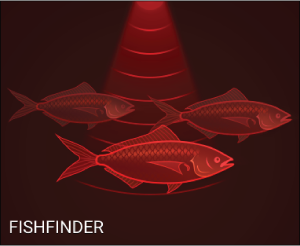
Fishfinder — The Fishfinder app uses a connected sonar module and transducer to help you to find fish by building up an underwater view of bottom structure and targets in the water column covered by your transducer. For more information refer to Fishfinder app |
|
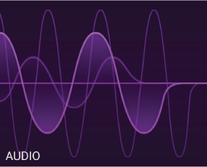
Audio — The Audio app allows you to control audio from a connected compatible entertainment system. For more information refer to Audio app |
|
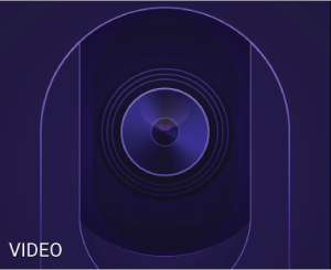
Video — The Camera app allows you to control and view feeds coming from connected video equipment such as an IP camera or Thermal camera. For more information refer to Video app |
|
Dashboard — The Dashboard app provides data readings from connected sensors and equipment. The Dashboard app is also used for controlling, configured, compatible, Digital Switching hardware. For more information refer to Dashboard app |
|
Yamaha — The Yamaha app provides data readings from connected Yamaha engines. For more information refer to Yamaha app |

|
PDF Viewer — The PDF Viewer app allows you to open PDF files located on your external storage. For more information refer to PDF Viewer app |
|
UAV — The UAV (Unmanned Aerial Vehicle) app provides remote controls, settings and video display, including flight data for your compatible UAV device. For more information refer to UAV (Unmanned Aerial Vehicle) app |
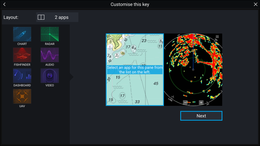
Creating / Customizing an App page
User profiles
|
Note:
User data such as Waypoints, Routes, Tracks, images and video recordings etc. will be available to all users, and are shared by all users. This means that, for example, if you add or delete a waypoint while using one user profile, the change will also be reflected in all other profiles on the MFD, including demo profiles. |
You can access the Profiles page by selecting the Profile Icon on the Homescreen.
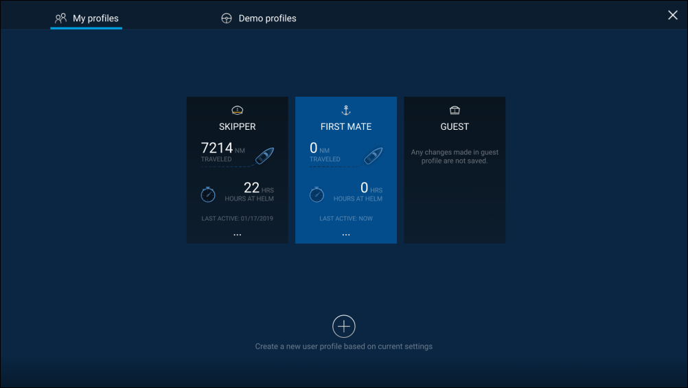
Selecting the Plus (+) icon will create a new profile based on the profile that is currently in use.
MFD settings changes are unique to the profile in use and are retained the next time the profile is used.
The distance and time that a profile has been active is displayed for each profile.
Profile names and icons can be customized. You can also reset the distance and time for each profile.
A Guest profile is available for temporary users. Setting changes to the Guest profile are not retained. Each time the Guest profile is activated the settings are based on the last used profile.
When the MFD is rebooted the last used profile will be active.
Demo profiles are also available to help you practice operating your MFD with simulated data.
Demo profiles
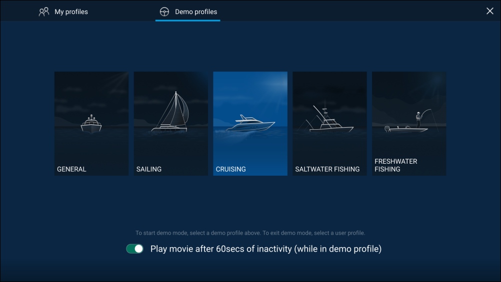
Selecting a Demo profile will provide your MFD with simulated data to help you practice operating your display.
Important:
|
Demo movie requirements
Demo movie files must be in the .mov file format and encoded using the H.264 video codec standard. The Demo movie files must be saved to an external storage device connected to the MFD. Demo movies are not shared across networked MFDs.
When the Demo movie feature is activated the system will search for a demo movie file associated with the active demo profile. If an associated file cannot be found then the generic demo.mov is played. See below for filename details.
| Demo profile | Associated filename |
|---|---|
| General |
demo_general.mov |
| Sailing |
demo_sailing.mov |
| Cruising |
demo_cruising.mov |
| Saltwater fishing |
demo_salt.mov |
| Freshwater fishing |
demo_fresh.mov |
|
Plays in all demo profiles if an associated demo file is not found. |
demo.mov |
If an MFD is powered off with the demo movie active then the next time the MFD is powered on the demo movie will play immediately after boot up.
Any interaction with the Touchscreen or physical buttons will stop the movie playing and return you to the active demo profile.
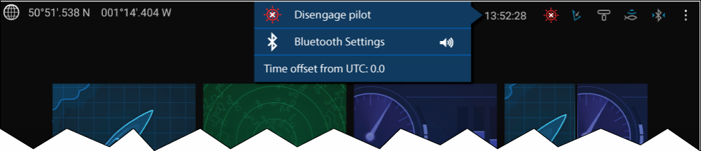
Status area
Status area icons
The status area provides icons which identify the status of connected Autopilot, AIS, Radar, Sonar/Transducer, and Bluetooth devices.
Pop-over menu options
From the Options pop-over you can:
- Disengage your autopilot.
- Access Bluetooth settings and volume controls.
- Adjust the Time offset from UTC.
Status area icons


Autopilot
|
Icon |
Status |
Icon |
Status |
|---|---|---|---|

|
Autopilot engaged |
Bluetooth
|
Icon |
Status |
Icon |
Status |
|---|---|---|---|
|
Bluetooth on / not connected |

|
Bluetooth connected / paired |
Radar
|
Icon |
Status |
Icon |
Status |
|---|---|---|---|

|
Radar transmitting |

|
Radar standby |

|
Radar error |
Sonar / Transducer
|
Icon |
Status |
Icon |
Status |
|---|---|---|---|
|
Sonar pinging |

|
Sonar not pinging |
|
Sonar error |
Touchlock
|
Icon |
Status |
Icon |
Status |
|---|---|---|---|

|
Touchlock active |
Satellite navigation / positioning
GNSS (GPS) Status
If latitude and longitude is displayed on the Homescreen, you have a valid position fix. If the text turns red, your fix accuracy is low.
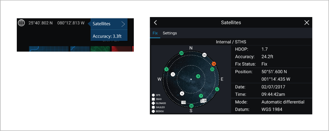
The sky view on the left side of the page shows the position of navigation satellites and the constellation they belong to. The color of the satellite identifies its status:
- Grey = searching for satellite.
- Green = satellite in use.
- Orange = tracking satellite.
GNSS (GPS) Settings
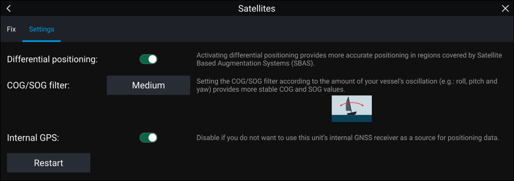
From the GNSS Settings tab you can:
- activate and deactivate use of Differential positioning (SBAS)
- set the COG/SOG filter according to your vessel’s oscillation, which provides more stable COG and SOG readings
- enable and disable your MFD’s internal GNSS (GPS) receiver. Disable it if you do not want to use this unit’s internal GNSS (GPS) receiver as a source for positioning data.
- restart the GNSS (GPS) receiver that is being used as the source for your positioning data.
My data
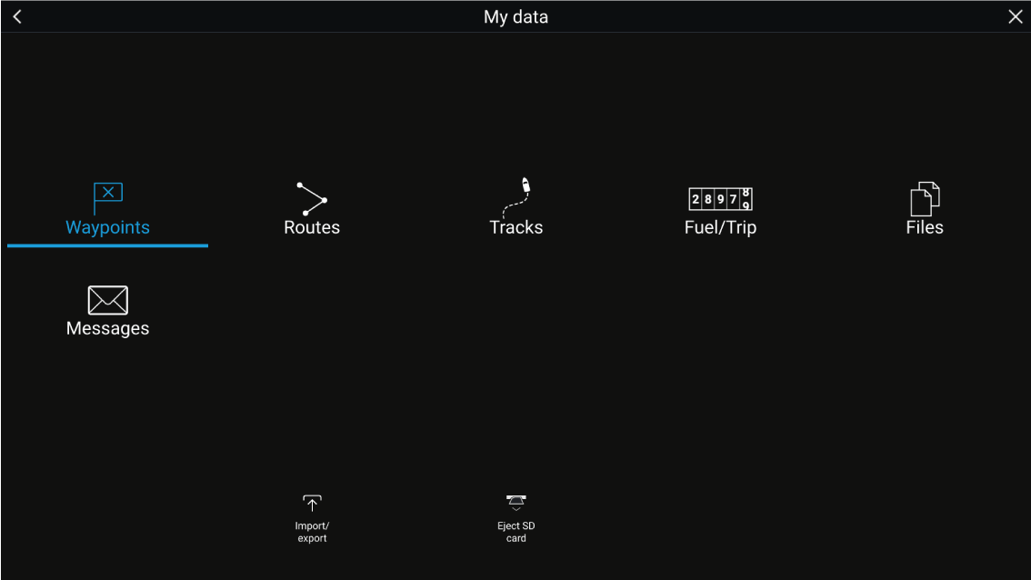
Selecting Waypoints, Routes or Tracks displays the relevant list, where you can manage and customize your data.
Selecting Fuel/Trip displays the Fuel manager and Trip counters.
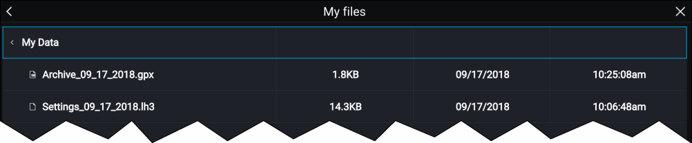
Selecting Files opens a file browser.
Selecting Import/export allows you to backup or restore user data and MFD settings using an external storage device.
Selecting Messages opens a list of secure messages you have sent from your system, or received from other first responder vessels. This feature requires an AIS5000 unit on the system, and the Responder settings must also be configured correctly. For more information, refer to: Responder setup
Fuel/trip manager
The Fuel/trip manager can be accessed by selecting Fuel/Trip from the My Data page: .

- Estimated fuel remaining
- Set all tanks full — Select when you have filled up all tanks.
-
Add partial fuel fill — Select to enter a specific volume of fuel during a partial tank fill.
Note: If you enter the wrong amount of fuel this can be corrected by entering a minus value as a partial fuel fill, this will reduce the total amount of fuel remaining by the amount entered. - Trip (Manual) — accumulates data until reset.
- Trip (Day) — resets automatically when local time passes midnight.
- Trip (Month) — resets automatically on the 1st day of the month.
- Trip (Season) — accumulates data until reset.
- Reset trip — The Trip (Manual) and Trip (Season) logs can be reset by selecting the relevant Reset Trip button.
Note:
|
Fuel set up
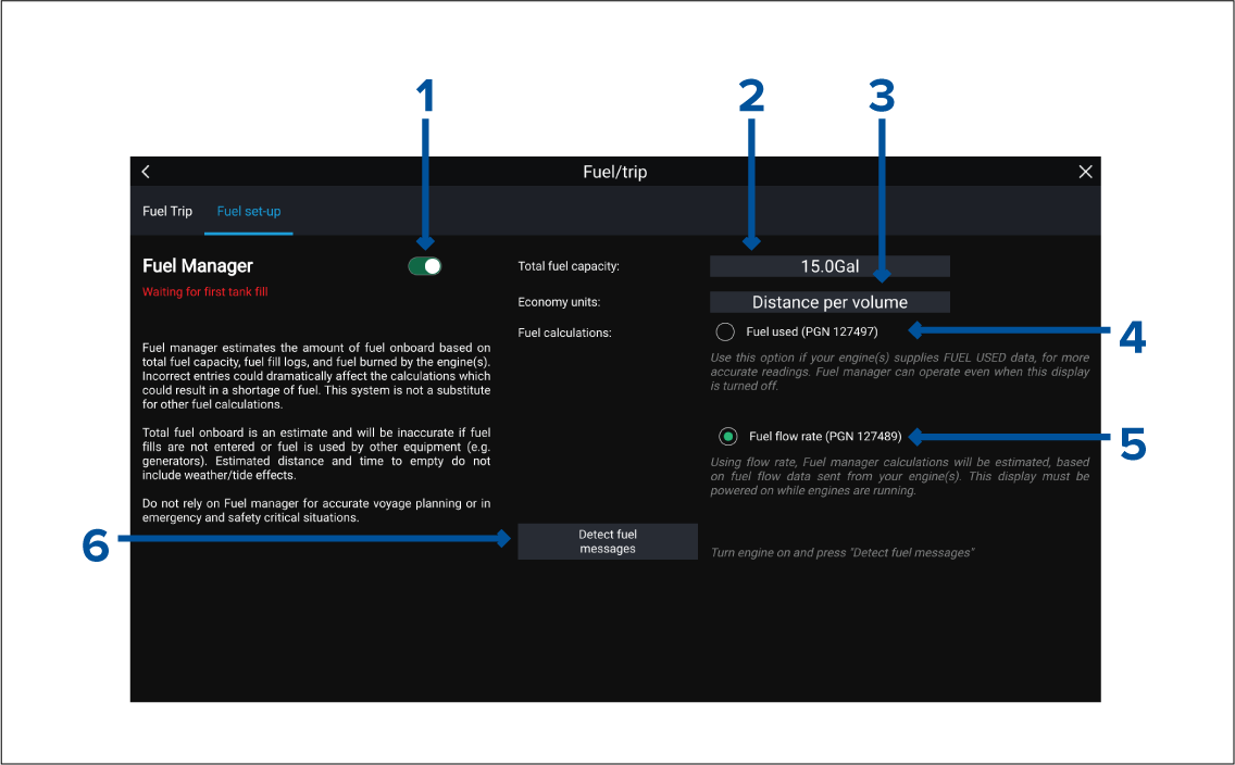
- Enable/Disable Fuel manager.
- Total fuel capacity — Sum of total capacity of all your fuel tanks.
- Economy units — Economy units used in data overlays, Side bars or the Dashboard app.
- Fuel used (PGN 127497) — Use this option if your engine(s) supply Fuel used data. When Fuel used is selected the Fuel manager will continue to operate when the MFD is switched off. This option usually provides more accurate readings.
- Fuel flow rate (PGN 127489) — this option estimates fuel calculations based on fuel flow rate data sent by your engine(s). Your MFD must remain switched on, whilst engines are running.
- Detect fuel messages — If you are unsure which engine messages your engine provides, select this option to determine the correct message.
Setting up the Fuel manager
Files
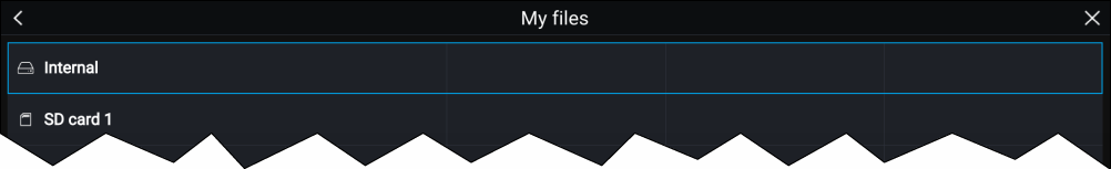
|
Note:
Only file types that are supported by your MFD will be visible in the browser. |
View PDFs
Import/export
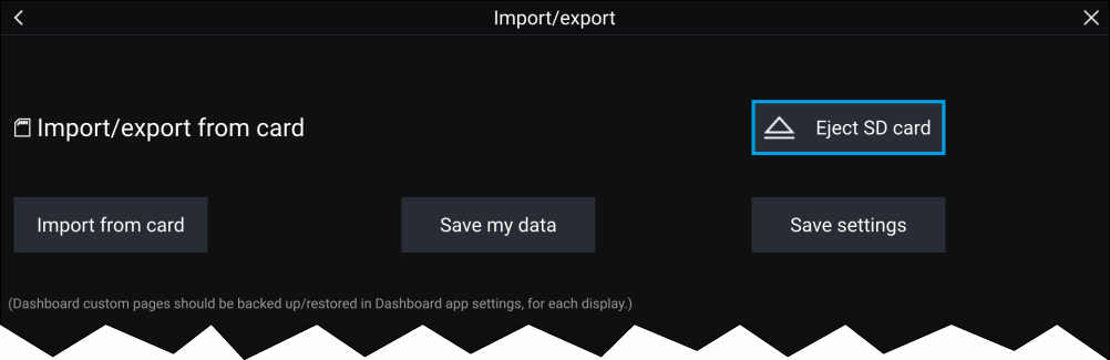
Saving user data (My data)
- Save all data to save (export) all waypoints, routes and tracks.
- Save waypoints to save (export) all waypoints.
- Save routes to save (export) all routes.
- Save tracks to save (export) all tracks.
The user data file is saved to the ‘\Raymarine\My Data\’ directory of your memory card in gpx format.
Saving MFD settings
Important:
|
Importing user data or MFD settings from a memory card
Important:
|
Secure messaging
|
Note:
For more information on responder setup refer to Responder setup |
Message inbox
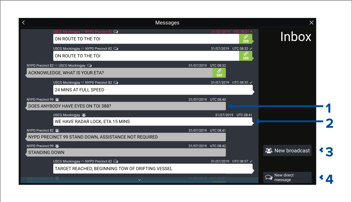
- Received broadcasts and direct messages (grey, left side).
- Sent broadcasts and direct messages (white, right side).
- New broadcast — Send a broadcast to all responder vessels.
- New direct message — Send a direct message to a specific responder vessel.
|
Note:
Messages older than 72 hours will be removed from the inbox after a power cycle. |
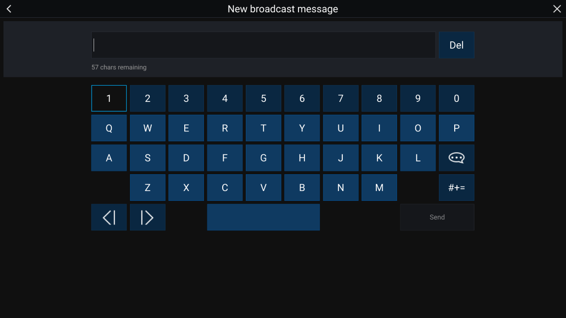
New broadcast
New broadcast opens the onscreen keyboard where you can type your broadcast message. When you are happy with your message select Send to broadcast the message.
New direct message
New direct message opens the Recipient page where you can select Recent (recent message senders and recipients) contacts and Buddy contacts.
Choose a recent or buddy contact and select Next to proceed to the onscreen keyboard. When you are happy with your message select Send to send the message.
If a recipient is not a Buddy contact and does not appear in the Recent list, you can manually enter their MMSI number to send them a direct message.
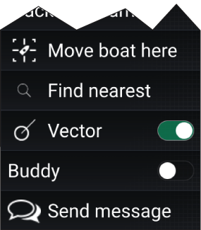
Direct messaging within the Chart or Radar app
Reply to messages
To reply, perform a long hold on a received direct message or broadcast until the context menu appears:
- Reply — Reply to a direct message with a direct message.
- Broadcast reply — Reply to a broadcast with a broadcast.
- Reply / Broadcast reply (with Link ID) — Reply to a direct message or broadcast that has a link ID by responding with a direct message or broadcast that contains the same link ID.
Onscreen keyboard

Message symbols

|
Broadcast — A broadcast to all other responder vessels. |
|

|
Direct message — A direct message to a specific responder vessel. |
|

|
Sender — Indicates the sender (left of the arrow) and recipient (right of the arrow) of a direct message. |
|

|
Message sent — Direct message has been sent and acknowledged by the recipient’s hardware. |
|

|
Message sending — Direct message is still waiting to be acknowledged as successfully received by the recipient’s hardware.
|
|

|
Message failed to send — Direct message has failed to be acknowledged by the recipient's hardware.
|
|

|
Link ID — A link ID generated and used by responder vessels.
|
Alarms
Alarms are color coded to signify their severity:
Dangerous alarms
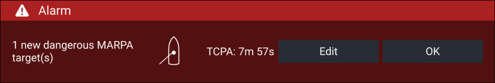
Red — A Red notification is used to signify a dangerous alarm condition, immediate action is required due to a potential or immediate danger to life or vessel. Dangerous alarms are accompanied by an audible tone. The Dangerous alarm notification and audible tone will continue to be displayed until acknowledged or the conditions that triggered the alarm are no longer present. Acknowledged alarms may remain active whilst the alarm condition persists but will not trigger further onscreen or audible notifications.
Warning alarms
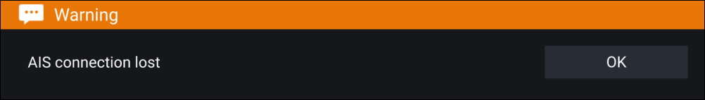
Orange — An Orange notification is used to signify a warning alarm condition. Warnings alarms are used to signify that there has been a change in situation that you need to be aware of. Warnings alarms are accompanied by an audible tone. The warning alarm notification and audible tone will continue to be displayed until acknowledged or the conditions that triggered the alarm are no longer present. Acknowledged alarms may remain active whilst the alarm condition persists but will not trigger further onscreen or audible notifications.
Notifications
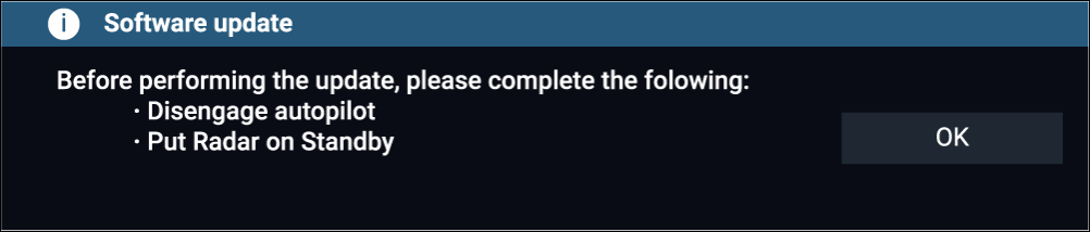
Blue — A Blue notification is used to signify information requiring user acknowledgement. Unless they require user interaction, information notifications may self dismiss after 3 seconds. Information notifications are not accompanied by an audible tone and are not displayed in the Active alarms or Alarm history lists.
Alarm manager
Active alarms
The Alarm manager can be accessed by selecting Alarms from the Homescreen.
Example: Active alarms tab
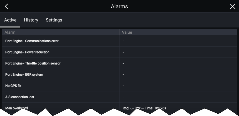
The Active alarms tab lists all alarms that are currently active. Alarms will remain active until the conditions that triggered the alarm are no longer present, e.g.: a Shallow depth alarm will automatically dismiss when the depth becomes deeper.
Alarm history
Example: Alarm history tab
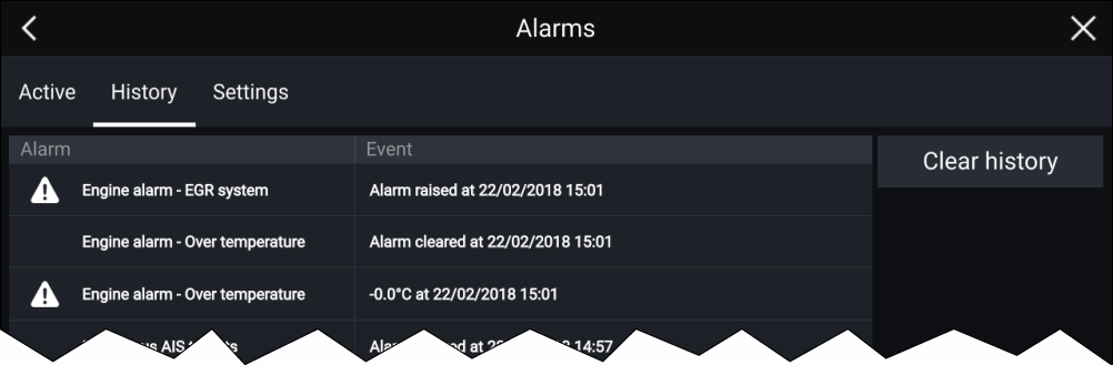
All Dangerous (Red) and Warning (Orange) alarms will appear in the Alarm history list. The history list will include an entry for the alarm being triggered (raised) and also for when the alarm is acknowledged (cleared). The Alarm field contains the name of the alarm and the events field contains details of the alarm condition and its time and date.
The Alarm history list can be cleared by selecting Clear history.
Active alarm indication
Active alarm indication can be enabled and disabled from the alarms settings tab: .
The Home icon will turn Red and have an exclamation mark placed inside it.
The Homescreen Alarms icon will display the number of active alarms.
Alarm settings
|
Alarm |
Description |
Options |
|---|---|---|
|
If enabled, an alarm is triggered when Radar targets become dangerous. Radar targets are deemed dangerous when they are within the specified:
|
|
|
|
If enabled, an alarm is triggered when dangerous Radar targets become lost (i.e.: no Radar return from the target has been received for 20 seconds). |
|
|
|
If enabled, an alarm is triggered when AIS targets become dangerous. AIS targets are deemed dangerous when they are within the specified:
|
|
|
|
If enabled, an alarm is triggered when Radar returns are detected within the specified guard zone 1. |
|
|
|
If enabled, an alarm is triggered when Radar returns are detected within the specified guard zone 2. |
|
|
|
If enabled, when you arrive at a waypoint, an alarm is triggered. This setting allows you to select one of three different types of radius, and then specify the radius size for the arrival alarm. When your vessel crosses this imaginary circle, the Waypoint Arrival alarm is triggered. |
|
|
|
Arrival radius — This value can be set when the MFD is NOT in pilot integration mode and the pilot is in Track mode. |
Radius can be set from 20 m to 10 NM. (Dependent on units of measure you specify for Distance units in System Settings). |
|
|
Pilot track mode radius — This can be used when the MFD is integrated with a pilot and the pilot is in Track mode. |
Radius can be set from 20 m to 10 NM. (Dependent on units of measure you specify for Distance units in System Settings). |
|
|
Search route arrival radius — This can be used when the MFD is following a SAR route. Also helpful when race sailing and using Laylines or when fishing, as this alarm setting provides a much tighter default radius to ensure you don't get alerted too far away from the target waypoint. |
Radius can be set from 3 m to 10 NM. (Dependent on units of measure you specify for Distance units in System Settings). |
|
|
If enabled, during active navigation an alarm is triggered when your vessel steers off track by more than the specified Cross track error value. |
Cross-track error value |
|
|
If enabled, an Alarm is triggered when your vessel drifts from your anchor position by more than the specified Drift range. |
Drift range value |
|
|
If enabled, an alarm is triggered when the fuel remaining in your fuel tanks reaches the Fuel level specified. The Fuel manager must be enabled for alarms to be triggered. |
Fuel level value |
|
|
If enabled, an alarm is triggered when DSC distress calls are received. A connected VHF radio is required in order to trigger DSC distress call alarms via the MFD. |
|
|
|
If enabled, an alarm is triggered when AIS safety messages are received. A connected AIS device is required in order to display AIS safety messages via the MFD. |
|
|
|
Determines whether the MOB waypoint is fixed at the position the alarm was triggered, or advances its position based on tide and wind effects. Dead reckoning normally provides a more accurate course. |
|
|
|
If enabled, an alarm is triggered when your Depth reading reaches the depth specified in Shallow water arrival or Deep water arrival. |
Shallow water arrival value Deep water arrival value |
|
|
If enabled, an alarm is triggered when the water temperature reading reaches the temperature specified in Lower temp limit or Upper temp limit. |
Lower temp limit value Upper temp limit value |
|
|
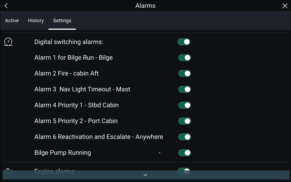
When your system includes Digital switching a list of all configured Digital switching alarms will be displayed. |
|
|
|
If enabled, AX8 camera messages will be presented as alarms on your MFD. A connected AX8 camera is required in order to display camera messages via the MFD. |
|
|
|
If enabled, alarms will be triggered when engine warning alarms are received from connected, compatible engine management systems or interfaces. |
|
|
|
Home button active alarm indicator |
If enabled, when an alarm is active the onscreen Home icon is colored Red and contains a warning triangle. |
|
External alarm speaker / buzzer
When connected to a Bluetooth speaker a separate volume control is available to control the volume of MFD Alarms sounded through the speaker. Please refer to the Bluetooth speaker pairing details.
Acknowledging alarms
|
Note:
If an alarm notification includes an Edit button, selecting it will display the relevant setting in the Alarms menu so that, if required, you can change the alarm threshold. |
Digital switching alarms
Man Overboard (MOB)
|
The MOB feature can be activated by pressing and holding on the MOB icon on the Homescreen. |
|
The MOB waypoint icon displayed at the top of all apps. |
The MOB feature requires your vessel to have a valid position fix from a GNSS (GPS) receiver. Dead reckoning mode also requires Heading and Speed data.
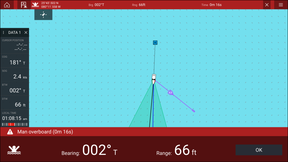
When you activate the MOB alarm:
- an audible alarm is sounded which is repeated every 30 seconds until the alarm is cancelled.
- a MOB Databar providing Bearing and range from MOB, and elapsed time since MOB was initiated, is displayed along the top of the screen. The Databar persists across apps and the Homescreen, and remains until the MOB alarm is cancelled.
- a MOB warning is displayed in the bottom of the screen, which requires acknowledgement.
- the Chart app is placed in a special MOB mode to help you navigate back to the point your vessel was at when the MOB was initiated.
MOB mode
MOB can be set to Dead Reckoning or Position mode. Dead Reckoning mode will take into consideration the effects of wind and tides. This usually provides a more accurate course. Position mode does not take these factors into account. You can change the MOB mode at anytime from the Alarms menu: .
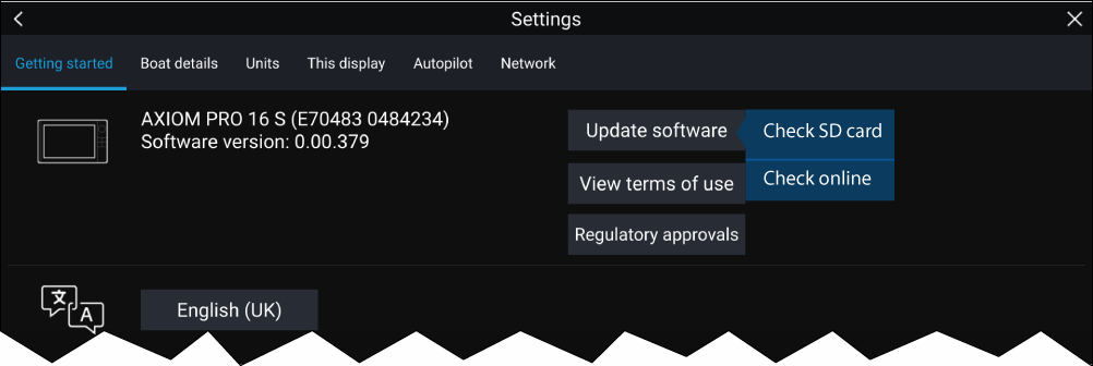
Settings
The Settings menu is divided into different tabs, the settings available are:
| Tab | Settings |
|---|---|
| Getting started |
|
| Boat details |
|
| Units |
|
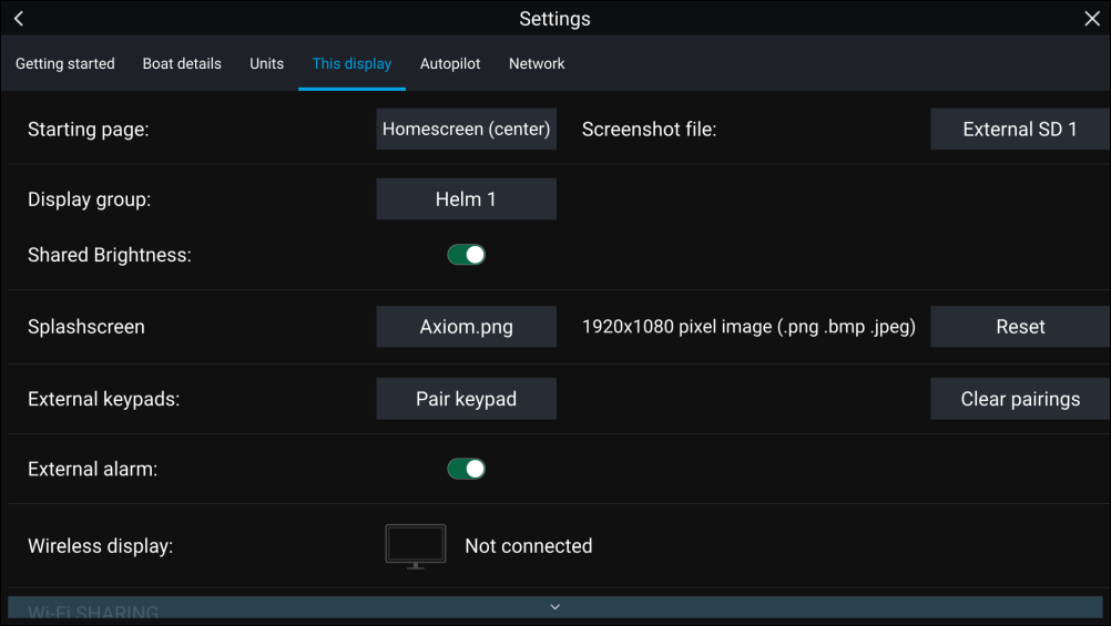
| This display |
|
| Autopilot |
|
| Network |
|
|
Responder
(Requires AIS5000 and boat activity set to First Responder) |
|
|
Note:
(1) Available on Axiom ™ Pro MFDs. (2) Available on Axiom ™ , Axiom ™ Pro and Axiom ™ XL MFDs. (3) Available on Axiom ™ XL and gS Series MFDs. (4) Available on Axiom ™ Pro, Axiom ™ XL, eS Series and gS Series MFDs. |
Selecting display language
User Interface languages
|
Arabic (ar-AE) |
Bulgarian (bg-BG) |
Chinese (Simplified) (zh-CN) |
Chinese (Traditional) (zh-TW) |
|
Croatian (hr-HR) |
Czech (cs-CZ) |
Danish (da-DK) |
Dutch (nl-NL) |
|
English (en-GB) |
English (en-US) |
Estonian (et-EE) |
Finnish (fi-FI) |
|
French (fr-FR) |
German (de-DE) |
Greek (el-GR) |
Hebrew (he-IL) |
|
Hungarian (he-IL) |
Icelandic (is-IS) |
Indonesian (Bahasa) (id-ID) |
Italian (it-IT) |
|
Japanese (ja-JP) |
Korean (ko-KR) |
Latvian (lv-LV) |
Lithuanian (lt-LT) |
|
Malay (Bahasa) (ms-MY ZSM) |
Norwegian (nb-NO) |
Polish (pl-PL) |
Portuguese (Brazilian) (pt-BR) |
|
Russian (ru-RU) |
Slovenian (sl-SI) |
Spanish (es-ES) |
Swedish (sv-SE) |
|
Thai (th-TH) |
Turkish (tr-TR) |
Vietnamese (vi-VN) |
Boat details
Boat details can be accessed from the Settings menu:
|
Option |
Description |
|---|---|
|
Selection determines the icon used to signify your vessel in the Chart app. |
|
|
Configures your system with your vessel’s name. |
|
|
[Sailing only] |
Select Fixed Angles or Polar laylines. |
|
[Sailing only] |
Select your vessel’s Boat type to provide more accurate leeway calculations. |
|
[Sailing only] [Fixed Angles only] |
Set the angle of upwind layline calculations. |
|
[Sailing only] [Fixed Angles only] |
Set the angle of downwind layline calculations. |
|
[Sailing only] [Polar only] |
Select the Polar table that will define your layline calculation. |
|
Enter your vessel’s maximum unladen height from the waterline. To ensure adequate clearance, it is recommended that you add a safety margin to this figure to allow for variation caused by vessel movements. |
|
|
Enter your vessel’s maximum width at its widest point. To ensure adequate clearance on both sides, it is recommended that you add a safety margin for port and starboard to this figure to allow for variation caused by vessel movements. |
|
|
Enter your vessel’s maximum depth when fully laden. This is the depth from the waterline to the lowest point on the vessel’s keel. To ensure adequate clearance, it is recommended that you add a safety margin to this figure to allow for variation caused by vessel movements. |
|
|
Select the number of engines on your vessel. When connected to a compatible system, your MFD can monitor engine data. |
|
|
Once you have selected the number of engines, select Identify engines and follow the onscreen instructions to configure your engines. May require an extra hardware interface to enable engine data to be displayed. |
|
|
Select your engine’s manufacturer. |
|
|
[Num of engines 2 only] |
Select whether your MFD is displaying for a twin engine system, or for the port or starboard side of a quad engine system. |
|
Configures your system with the number of batteries on your vessel. |
|
|
Calibrate your vessel’s tanks. |
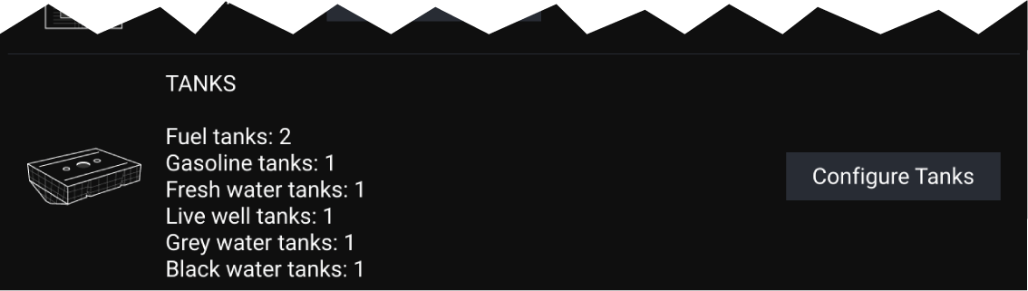
Calibrating tanks
Tanks can be calibrated and edited on the Boat details page: .
Tanks can be calibrated with the following Oceanic Systems tank senders:
- 3271 Volumetric Fuel Sender
- 3281 Water Level Senders
- 3125 Tank Sender Adapter
- 4291 Tank Level Adapter
|
Note:
|
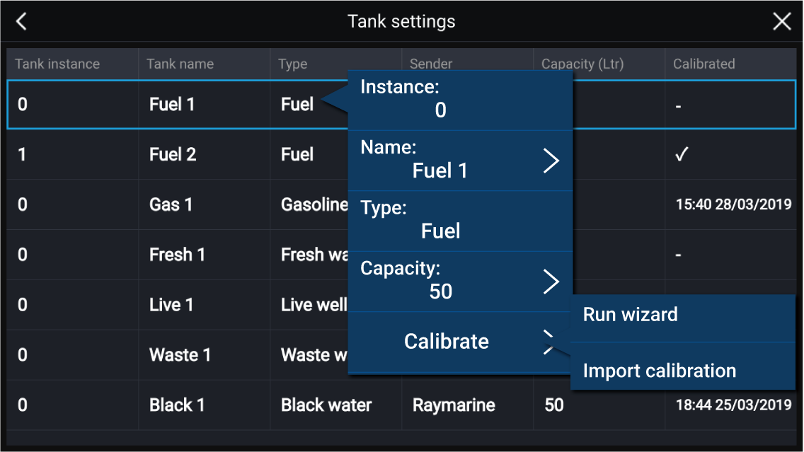
Run wizard calibration
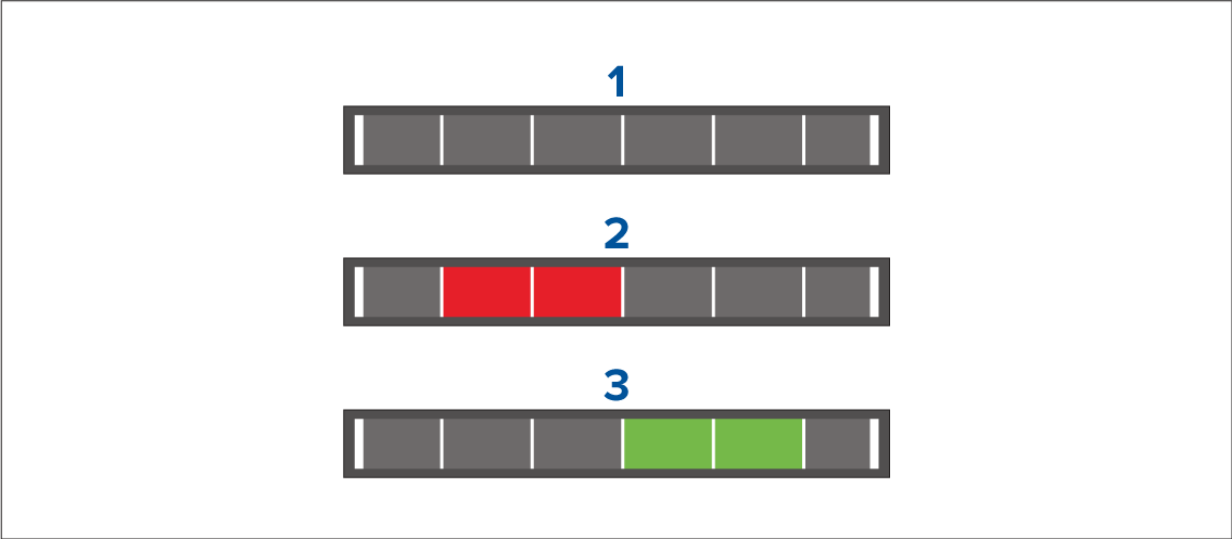
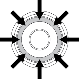
The shape of your tank determines how many calibration points you should enter for calibration. 2 calibration points are required as a minimum, but up to 101 points can be entered. Generally, the more calibration points entered the more precise tank readings will be.
Additional calibration points are used to account for changes in tank volume at different parts of an irregularly shaped tank. Depending on the size and shape of your tank it is recommended that you enter calibration points to mark each change in the shape of the fuel tank; for example, straight corners require an additional point, and slopes require 2 points.
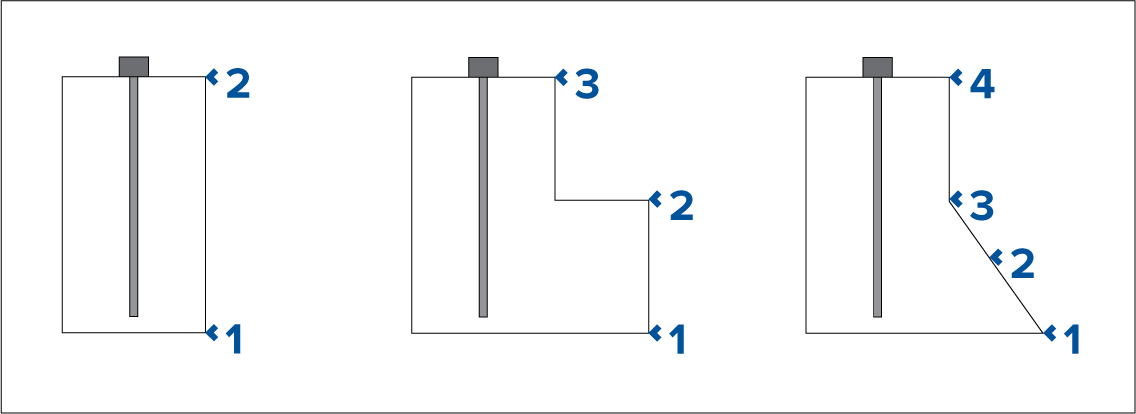
The illustration above shows the minimum number of calibration points recommended for some typical tank shapes:
- The tank shown on the left is rectangular and symmetrical; it only requires 2 calibration points to define the bottom and top of the tank.
- The tank shown in the center has a greater volume at the bottom; 3 points are required to define the bottom, top and corner of the fuel tank.
- The tank shown on the right has a greater volume at the bottom and is sloped. 4 points are required to define the bottom of the tank, the top, and a further 2 points to define the slope.
Wizard Calibration
Import calibration
Units of measure
| Measurement | Units |
|---|---|
|
Distance units |
|
|
Speed units |
|
|
Depth units |
|
|
Temperature units |
|
|
Date format |
|
|
Volume units |
|
|
Economy units |
|
|
Wind speed units |
|
|
Pressure units |
|
|
Time format |
|
Data master
Information shared by the Data master includes:
- Cartography
- Waypoints, Routes and Tracks
- Radar
- Sonar
- Data received from the autopilot, GNSS (GPS) receiver, instruments, transducers, the engine and any other compatible external sources.
| Note: Your system may be wired for redundancy with data connections made to repeat displays. However these connections will only become active in the event of a fault and / or reassignment of the data master. |
Shared Brightness
The following products are compatible with shared brightness:
- LightHouse ™ 3 MFDs using software version 3.4 or greater.
- LightHouse ™ or LightHouse ™ 2 powered MFDs.
- SeaTalkng ® Instrument displays and Pilot controllers.
- SeaTalkng ® VHF DSC Radios.
- RMK-9 and RMK-10 remote buttonpads.
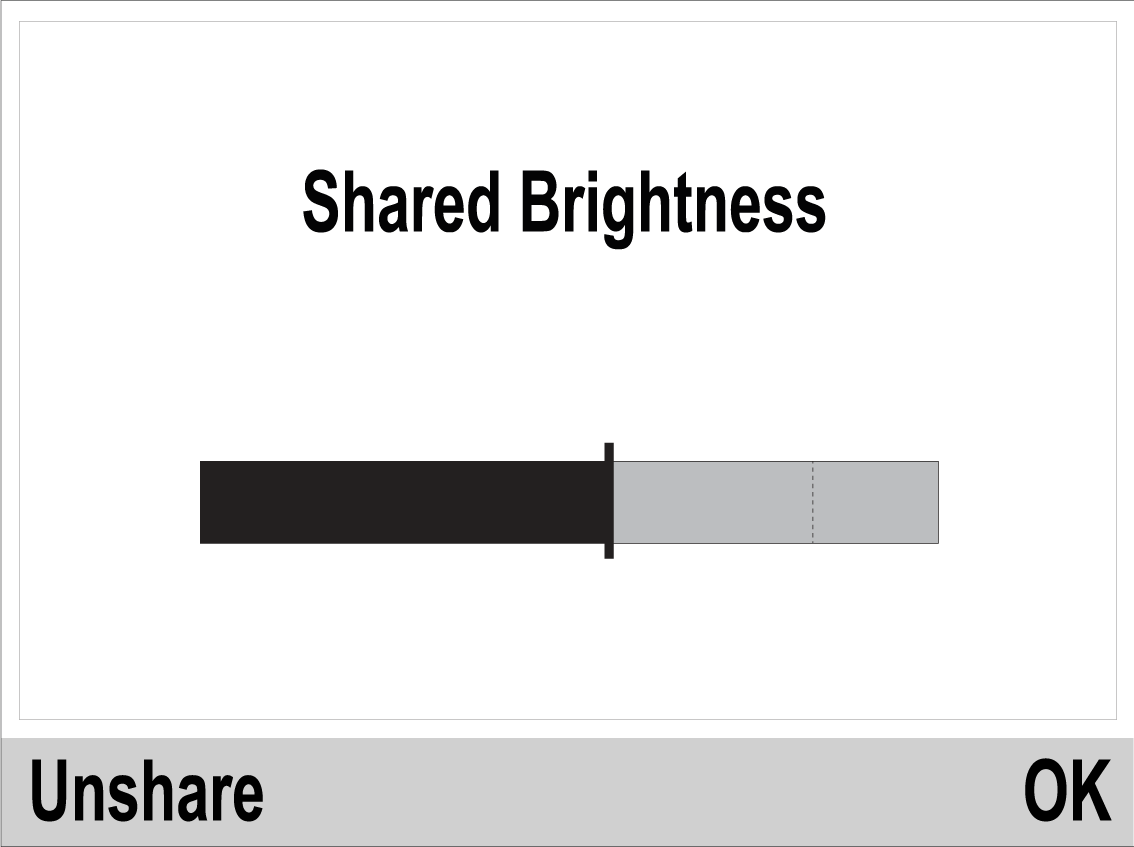
Any adjustments to the shared brightness level will be applied to all products assigned to the same group.
|
LightHouse ™ / LightHouse ™ 2 MFD |
Instrument display / Pilot controller |
|---|---|
|
|
|
VHF DSC Radio |
LightHouse ™ 3 V3.4 or greater |
|
|
Multiple brightness groups can be configured. For example, these groups could be used to reflect the physical location of products on your vessel e.g.: helm and flybridge.
Shared brightness requires:
- all products to be compatible with the shared brightness function (see list of compatible products above).
- the Shared brightness setting set to On for all products in the brightness group.
- products to be assigned to network groups.
- all the products in each group to be synchronized.
Customizing the splashscreen
- The customized image must be in .png, .bmp or .jpg format.
- Custom images cannot exceed the maximum resolution supported by your MFD.
- For optimum image quality, the resolution of the splashscreen image should match the resolution of your MFD. Refer to the following table: Axiom screen resolutions.
Note:
|
The next time your MFD powers up, your custom image will be displayed.
Axiom screen resolutions
|
MFD variant |
Screen resolution (W x H) |
|---|---|
|
Axiom ™ 7+ |
1024 x 600 |
|
Axiom ™ 9+ |
1080 x 720 |
|
Axiom ™ 12+ |
1280 x 800 |
|
Axiom ™ 7 |
800 x 480 |
|
Axiom ™ 9 |
800 x 480 |
|
Axiom ™ 12 |
1280 x 800 |
|
Axiom ™ Pro 9 |
1280 x 720 |
|
Axiom ™ Pro 12 |
1280 x 800 |
|
Axiom ™ Pro 16 |
1920 x 1080 |
|
Axiom ™ XL 16 |
1920 x 1080 |
|
Axiom ™ XL 19 |
1920 x 1080 |
|
Axiom ™ XL 22 |
1920 x 1080 |
|
Axiom ™ XL 24 |
1920 x 1200 |
NMEA 0183 settings
2 NMEA 0183 ports are available:
- Port 1: Input and output, 4,800 or 38,400 baud rate.
- Port 2: Input only, 4,800 or 38,400 baud rate.
The baud rate for each input port must be specified in the NMEA set-up menu ().
Note:
|
NMEA 0183 settings
|
Menu item |
Description |
Options |
|
|---|---|---|---|
|
NMEA Port 1 |
Baud rate selection. |
|
|
|
NMEA input port 2 |
Baud rate selection. |
|
|
|
Bridge heading |
Bridge heading data from NMEA 0183 to NMEA 2000 / SeaTalkng ® |
|
|
|
Transmission mode |
Switches between Single-ended and Differential transmission modes. The Differential transmission mode supports higher speeds, longer cable runs, and better data integrity. Differential mode works when connected to opto-isolated inputs, as specified by the NMEA 0183 standard. The Single-ended mode is required when sending a signal to a single-ended receiver device, such as a PC for example. Refer to the NMEA 0400 Installation Standard for wiring guidelines for the different transmission modes.
|
|
|
|
Individual outputs |
List of NMEA 0183 sentences for which the output can be disabled. |
|
Responder setup
Note:
|
Connecting to a wireless display
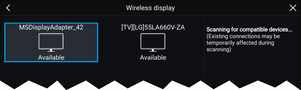
Note:
|
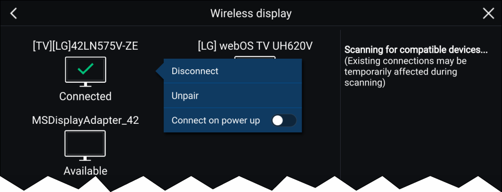
Disconnecting a wireless display
Unpairing a wireless display
Autopilot control
Autopilot control
Autopilot control from your MFD can be enabled and disabled from the Autopilot tab in the Settings menu: .
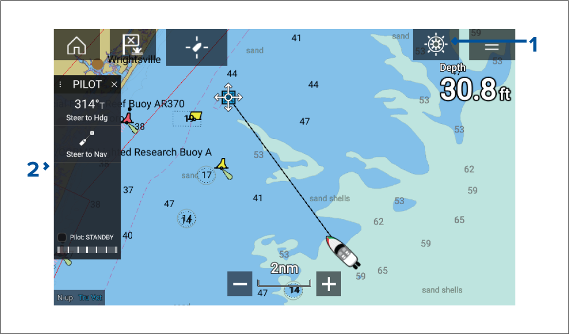
- Pilot icon — With Autopilot control enabled, the Pilot icon is displayed onscreen; selecting the icon displays the Pilot sidebar. When the Autopilot is engaged the Pilot icon is replaced with the Disengage pilot icon.
- Pilot sidebar — The Pilot sidebar provides controls and information relating to your autopilot system. With the Autopilot engaged the Pilot sidebar’s content is expanded to provide further controls and information. The Pilot sidebar can be hidden by swiping the sidebar to the left. The sidebar can be displayed again by swiping from the left of the screen towards the center of the screen.
Engaging the autopilot — Locked heading
Engaging and disengaging the autopilot - physical buttons
Pilot sidebar
| Note: The Pilot sidebar is controlled using the Touchscreen. |
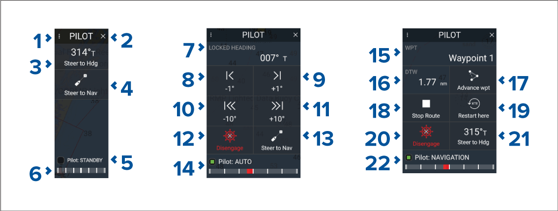
Pilot sidebar — Standby
|
1 |
Sidebar selection
Enables you to switch between Pilot and Data sidebars. |
|
2 |
Close
Closes the Pilot sidebar. |
|
3 |
Steer to Hdg
Enables you to engage the autopilot in locked heading (Auto) mode. |
|
4 |
Steer to Nav
Enables you to engage the autopilot in Navigation (Track) mode. |
|
5 |
Pilot status
Provides the status of the autopilot. |
|
6 |
Rudder bar
Provides visual indication of rudder position. |
|
7 |
Heading
Displays your autopilot’s current locked heading. Selecting displays the Locked Heading adjustment pop-over. |
|
8 |
–1
°
Selecting will adjust your locked heading by minus 1 degree. |
|
9 |
+1
°
Selecting will adjust your locked heading by plus 1 degree. |
|
10 |
–10
°
Selecting will adjust your locked heading by minus 10 degrees. |
|
11 |
+10
°
Selecting will adjust your locked heading by plus 10 degrees. |
|
12 |
Disengage
Selecting will disengage your autopilot. |
|
13 |
Steer to Nav
Selecting will engage your autopilot in Navigation mode. |
|
14 |
Pilot state
Displays the current state / mode of your autopilot. |
|
15 |
Destination
Displays your current destination. |
|
16 |
User customizable data
Displays user customizable data. Select to customize data. |
|
17 |
Advance wpt
Selecting will advance your destination to the next waypoint in the current route. |
|
18 |
Stop Route / Stop Goto
Selecting will stop current navigation. |
|
19 |
Restart here
Selecting will restart the cross track error (XTE) at your current location. |
|
20 |
Disengage
Selecting will disengage your autopilot. |
|
21 |
Steer to Hdg
Selecting will switch your autopilot to Locked heading mode. |
|
22 |
Pilot state
Displays the current state / mode of your autopilot. |
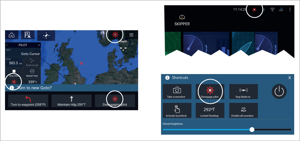
Pilot pop-up
Goto
When performing a Goto the Pilot pop-up provides options to disengage the autopilot or to maintain the current course in Locked heading mode.
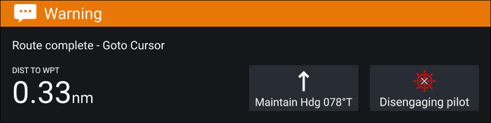
Follow
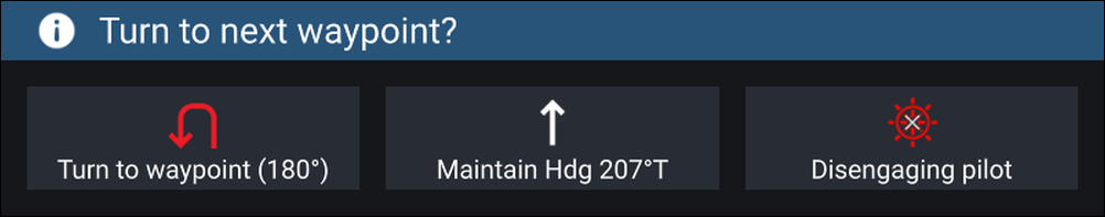
When following a Route the Pilot pop-up provides options to make the required turn to the next waypoint, disengage the autopilot or to maintain the current course in Locked heading mode.
Autopilot Control — Advanced settings
|
Menu item |
Description |
Options |
|---|---|---|
|
Selecting the hull type that is the closest match for your vessel provides optimum steering performance. |
|
|
|
Selecting the drive type that matches your vessel’s drive will provide optimum drive performance. |
List of drives compatible with your ACU. |
|
|
Adjust the Compass offset so that your autopilot’s heading matches the ship’s compass. The display of autopilot heading data requires a second networked MFD or pilot controller. Compass offset will be adjusted automatically during the Align compass to GPS procedure. |
|
|
|
Selects the source for speed data. |
|
|
|
Set the Cruise speed value to your vessel’s typical cruising speed. |
|
|
|
The calibration lock is used to lock out specific calibration settings which if changed may require recommissioning of the autopilot system. If your system has been dealer installed then the lock may be turned on. |
|
|
|
Dockside calibration must be carried out before using your autopilot for the first time. The Dockside wizard guides you through the dockside calibration process. The steps included in the dockside wizard are dependent on whether you have a rudder reference transducer fitted to your vessel. |
|
|
|
Select to restart the compass linearization procedure. |
|
|
|
Locks the compass linearization so that further automatic linearization is not performed. |
|
|
|
Follow the onscreen instructions to align your compass with your GPS heading. |
||
|
Resets your autopilot’s settings to factory default values. |
|
|
|
Sets a debug value for troubleshooting purposes. The debug level should only be set when requested by Technical Support as part of a troubleshooting process. |
|
|
|
Sets a debug value for troubleshooting purposes. The debug level should only be set when requested by Technical Support as part of a troubleshooting process. |
|
|
|
Rudder damping is used to prevent the autopilot from “hunting” maneuvers. Always use the lowest acceptable value. |
|
|
|
Determines the amount of course change when performing an auto turn. |
|
|
|
Determines the behavior of the Rotary or Joystick. |
|
|
|
Inverts the rudder reference display graphic. |
|
|
|
Switches the polarity of your drive motor. |
|
|
|
Adjust to specify the rudder offset from amidships. |
|
|
|
Specifies how far the rudder can move before hitting its end stops. The value should be set to approximately 5° less than your maximum rudder angle. |
|
|
|
Specifies the time it takes for the rudder to move from hard port to hard starboard or vice versa. The default value is determined by your Drive type selection. |
|
|
|
When set to Prevent Gybe the autopilot will prevent you from performing an Auto tack away from the wind. |
|
|
|
Selects whether wind data is True or Apparent. |
|
|
|
Enables and disables the Wind shift alarm. |
|
|
Note:
(1) Option not available when Calibration lock is On. (2) Only available when Vessel hull type is set to a Sailing vessel. (3) Only available when a rudder reference transducer is connected. |
Waypoints, Routes and Tracks
Waypoints
Waypoints are used to mark specific locations or points of interest. Waypoints can be used in the Chart, Radar and Fishfinder apps. Your MFD can store up to 10,000 waypoints which can be sorted into up to 200 waypoint groups.
In the Chart app you can navigate to a waypoint by selecting Goto from the Waypoint context menu.
Placing a waypoint
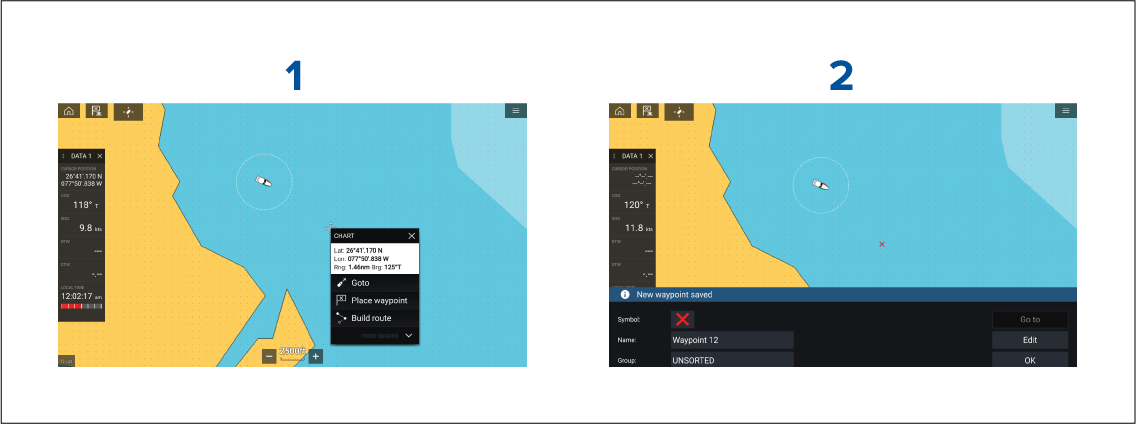
Placing a waypoint at a specified lat/long
Waypoint management
The Waypoint list can be accessed from the Homescreen and from the Chart app: , or .
Waypoint list
The Waypoint list is sorted into groups. Selecting a group displays a list of all the waypoints included in that group. Selecting a waypoint displays the customizable details for that waypoint.
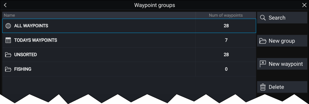
From the Waypoint list you can Search for a waypoint, Create a New group, Create a New Waypoint or Delete a waypoint group.
Selecting a Waypoint group from the list displays a list of all waypoints in that group.
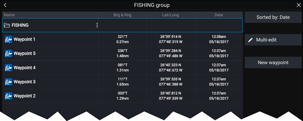
Group lists
If the Waypoint list is accessed from the Chart app menu, the selected group or waypoint is displayed in a Chart pane on the right of the screen.
You can Rename, Delete or Hide/Show the group by selecting the Group name at the top of the list.
From the group list you can change the list sort order, Hide/Show the Waypoint group in the current Chart app instance or create a New waypoint.
Use the Multi-edit option to make the same change to multiple Waypoints (e.g. change symbol, delete waypoints or move to a different group).
Select a waypoint to view its details.
Waypoint details
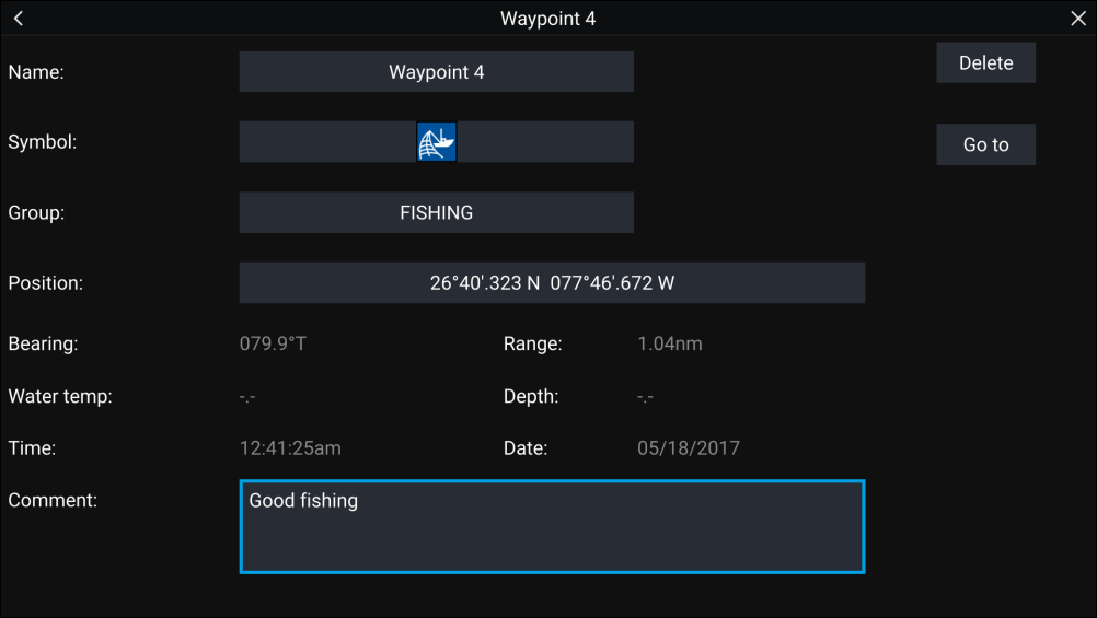
The details for the waypoint can be customized by selecting the relevant field. You can also Delete the waypoint, set a Goto, or View on chart.
Routes
Routes are used to plan your journey in advance. You can plan your journey directly on your MFD, or at home using software capable of exporting Waypoints and Routes in standard .gpx format, such as Raymarine’s Voyage Planner software.
Routes consist of a number of waypoints. Your MFD can store up to 250 Routes, each Route consisting of up to 500 waypoints. The Route capacity limit is subject to your MFD’s 10,000 Waypoint limit (for example, your MFD could store 20 Routes each containing 500 waypoints).
Creating a Route
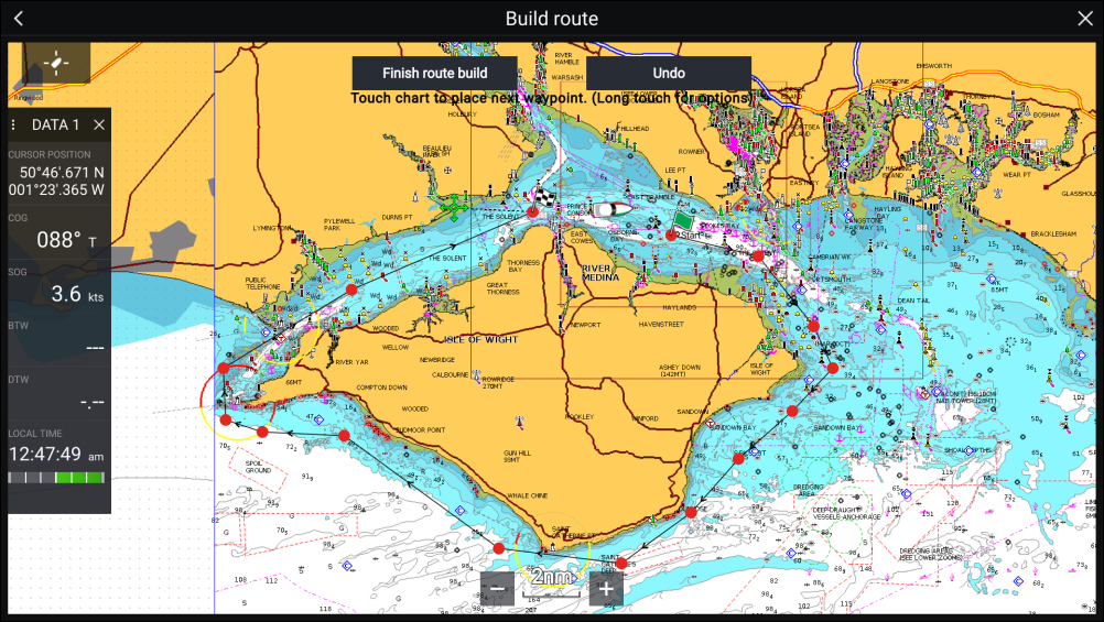
Use Autorouting during route creation
Autorouting
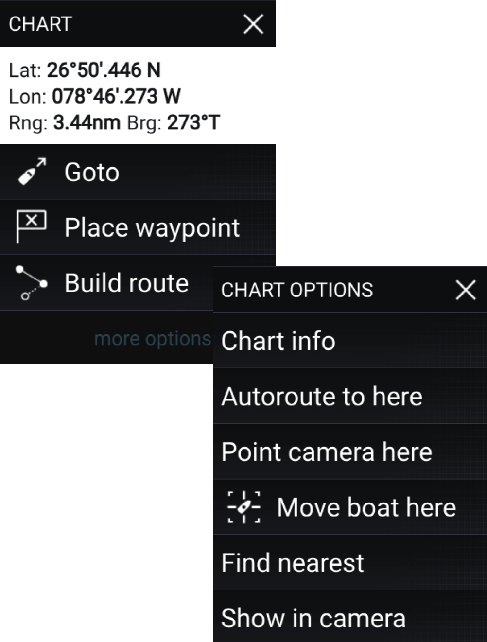
You can select any point on the Chart and from the Chart context menu select Autoroute to here or you can select Autoroute to from an existing waypoint’s context menu to create a route automatically between your vessel and the chosen point.
The created route is generated by comparing data available on your cartography against the minimum safe distances specified in the Boat details menu: ().
Waypoints will not be placed in areas that conflict with your specified minimum safe distances. Caution symbols are used for waypoints that are near objects or restricted areas.
Never follow a route before checking each route leg is safe for your vessel.
Reviewing an automatically generated route
Importing a route
Route management
The Route list can be accessed from the Homescreen and from the Chart app: , or .
If the Route list is accessed from the Chart app menu, then the selected route is displayed in a Chart pane on the right of the screen.
Route list
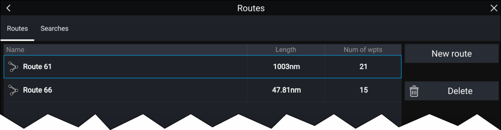
From the route list you can Delete routes or create a New route using existing waypoints.
To view a route plan, select a route and choose View route plan.
Route plan
The route plan displays a list of all waypoints in the route and when accessed from the Chart app also includes a Chart pane showing the route’s location.
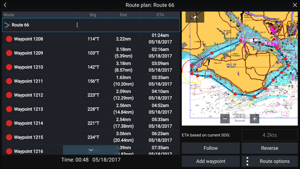
From the Route plan you can:
- navigate the route by selecting Follow
- change the route direction by selecting Reverse
- add an existing waypoint to the route by selecting Add waypoint
- change route options by selecting Route options
By selecting a waypoint from the route plan you can change the waypoint order by moving the waypoint up and down the list. You can also remove the waypoint from the list, delete the waypoint, edit the waypoint details or start the Route follow from any waypoint in the route.
Route options
| Rename route |
Give the route a name. |
| Color |
Change the color of the route, as displayed in the Chart app. |
| Time |
Switch the time between ETA (Estimated Time of Arrival) and TTG (Time To Go). |
| Speed |
Switch the speed between Actual (SOG) and Planned. When the speed is set to Planned you can select a desired speed for navigating the route. |
| Hide/show on chart |
Choose whether the Route should be displayed in the Chart app or not. |
| Export |
Export the route to a memory card. |
| Delete route |
Delete the route. |
Tracks
Tracks are used to record where you have been. Tracks are made up of track points that are created at regular time or distance intervals. You can store up to 15 tracks on your display, each track can contain up to 10,000 points.
Tracks can be converted into routes so that they can be followed.
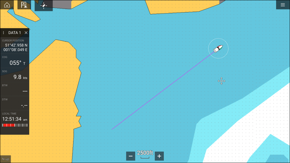
Creating a track
Converting a track to a route
Track management
The Track list can be accessed from the Homescreen and from the Chart app: , or .
If the Track list is accessed from the Chart app menu, then the selected track is displayed in a Chart pane on the right of the screen.
Track list
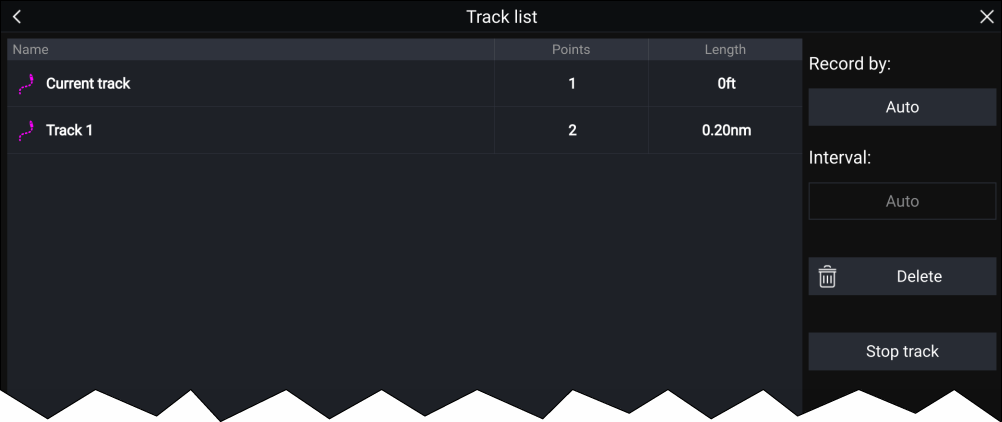
From the track list you can Start or Stop tracks recording, Delete a track or choose how tracks are recorded.
Track interval
The track interval determines the time period or distance between track points when recording a track. You can choose whether to record track points by Time, by Distance or set to Auto.
- In Auto the track interval is set automatically to minimize the track points used whilst maintaining the actual path taken.
- When set to Time, you can choose a specified time period between track points.
- When set to Distance you can choose a specified distance between track points.
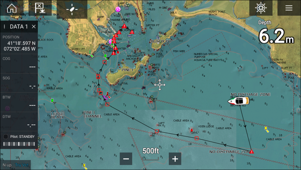
Chart app
Chart app overview
For each instance of the Chart app you can select which electronic cartography you want to use. The selection will persist over a power cycle.
The Chart app can be displayed in both fullscreen and splitscreen app pages. App pages may consist of up to 4 instances of the Chart app.
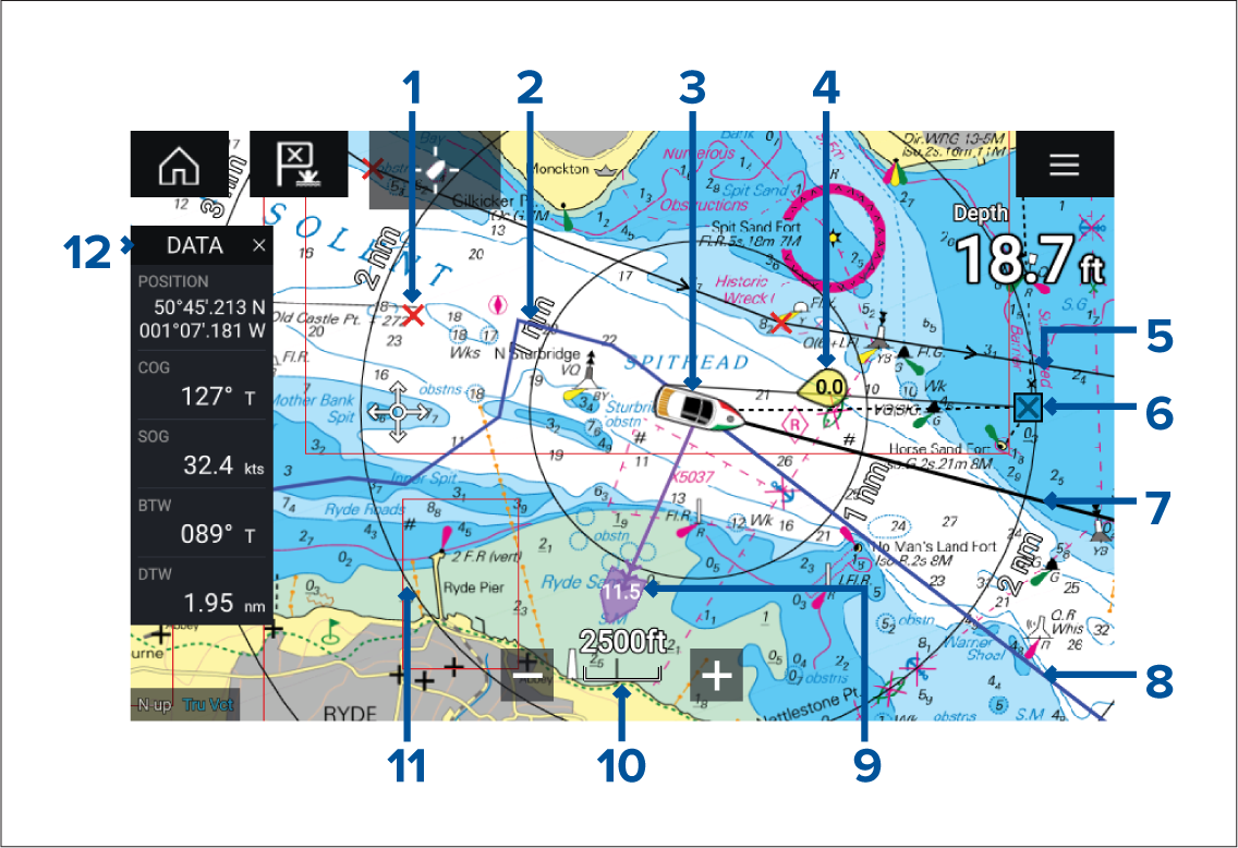
|
1 |
Waypoint Use waypoints to mark specific locations or points of interest. |
2 |
Track You can record the passage your vessel takes using Tracks. |
|
3 |
Vessel icon This icon represents your vessel, only displayed when a GNSS (GPS) position fix is available. The icon will be a black dot if no Heading is available). |
4 |
Wind indicator Provides indication of wind direction and speed (Wind transducer required). |
|
5 |
Route You can plan your route in advance by creating a Route using Waypoints to mark each route leg. |
6 |
Destination waypoint During a Goto, this is the current destination waypoint. |
|
7 |
Heading line If Heading data is available, a Heading vector for your vessel can be displayed. |
8 |
COG line If COG data is available, you can display a COG vector for your vessel. |
|
9 |
Tide indicator Provides tide Set and Drift indicators. Requires the following data: COG, Heading, SOG, and STW (Speed Through Water). |
10 |
Chart range Identifies the scale for the displayed Chart range. |
|
11 |
Range rings Provides a distance indication around your vessel at set intervals. |
12 |
Sidebar The Sidebar contains system data that can be viewed in all apps. |
Chart app controls
| Icon | Description | Action |
|---|---|---|

|
Home icon |
Takes you to the Homescreen |

|
Waypoint / MOB |
Place waypoint / hold down to activate Man overboard (MOB) alarm |
|
Pilot icon |
Opens and closes the Pilot Sidebar |

|
Menu icon |
Opens the app menu |

|
Find vessel |
Centers your vessel onscreen. |

|
Range In |
Decreases the range/distance displayed onscreen. |

|
Range Out |
Increases the range/distance displayed onscreen. |
Chart ranging and panning
You can change the range displayed in the Chart app using the onscreen Range controls or by using the pinch-to-zoom multi-touch gesture.
You can pan the chart area by swiping your finger across the chart.
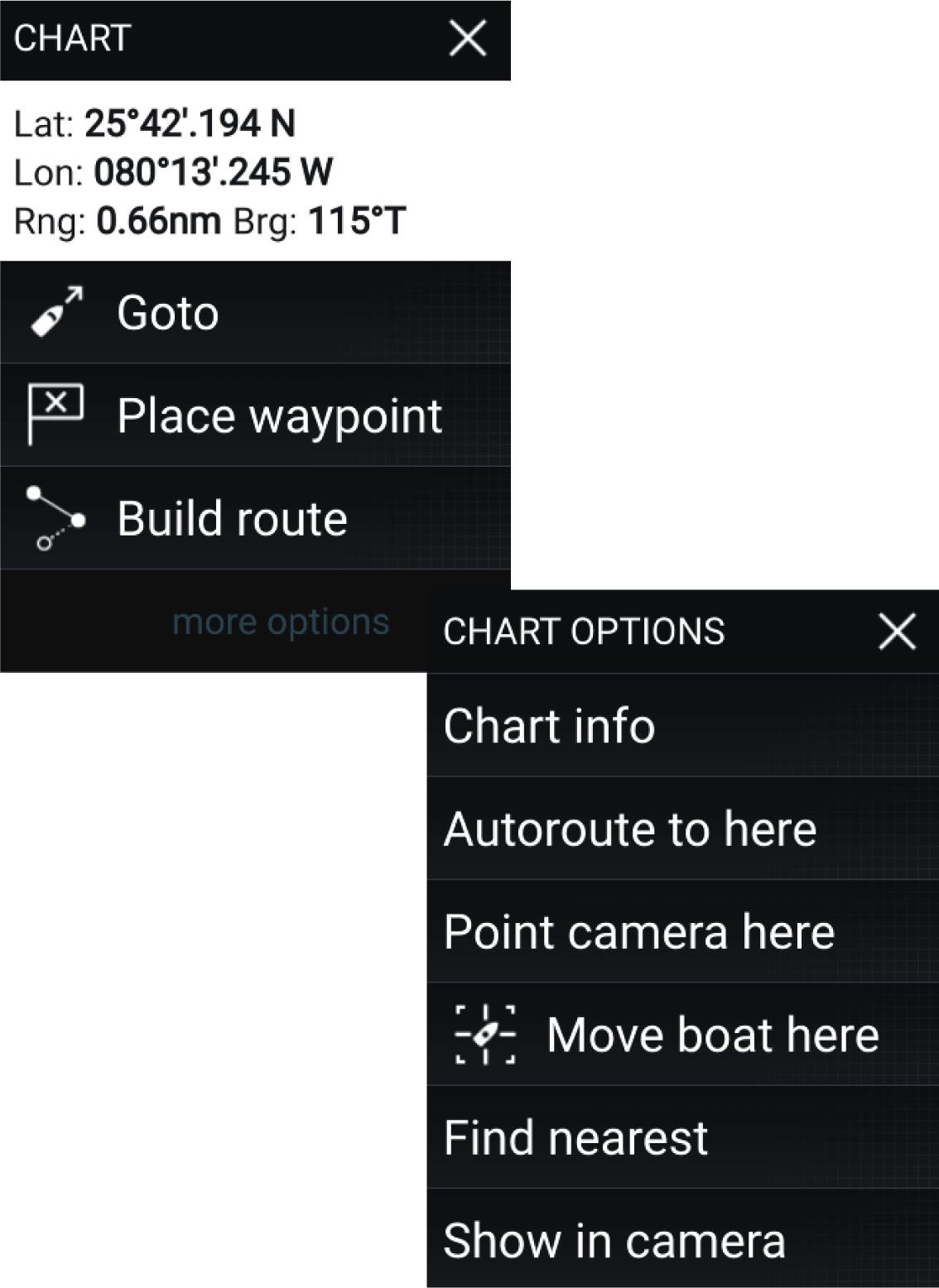
Chart app context menu
Selecting a chart card
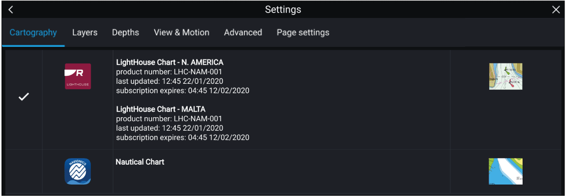
|
Note:
If no chart cards are detected on your MFD network the Chart app will default to Lighthouse Chart cartography. |
LightHouse charts
There are 2 main types of LightHouse chart:
Standard — LightHouse charts provide enhanced shoreline and street detail. Standard LightHouse charts also feature a “Leisure” style presentation for general use, or “Government” style presentation for advanced users.
Premium — LightHouse charts can also be enhanced with the Premium tier subscription. Premium customers receive access to Premium Points Of Interest (POI), Satellite Imagery, and the addition of new features on a regular basis, as soon as they become available.
| Note: For more information on the latest features and regions available with LightHouse Standard and Premium charts, visit the Raymarine website: https://www.raymarine.com/marine-charts/lighthouse-charts.html |
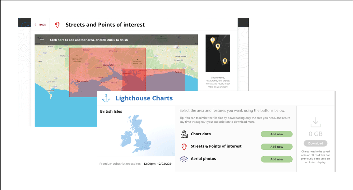
LightHouse Premium
With Lighthouse Premium charts, you can choose the regions you require, as well as the level of detail.
The latest chart features are available to Premium chart users as soon as they become available. LightHouse Premium charts can be downloaded to your MFD via an SD card, or via the RayConnect app.
LightHouse Premium users have access to the following additional Chart features at launch, with more features added on a regular basis:
- Premium Points Of Interest (POI)
- Premium Satellite Images
- Regular Updates
Lighthouse Premium subscription
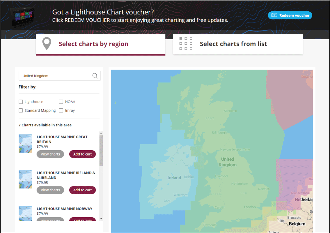
Available LightHouse Chart Regions:
|
Note:
New regions are being added to LightHouse Charts regularly, please check the website for available regions https://www.raymarine.com/marine-charts/lighthouse-charts.html |
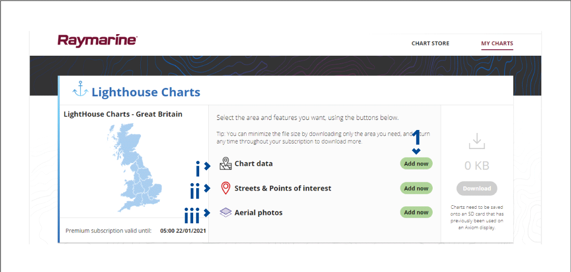
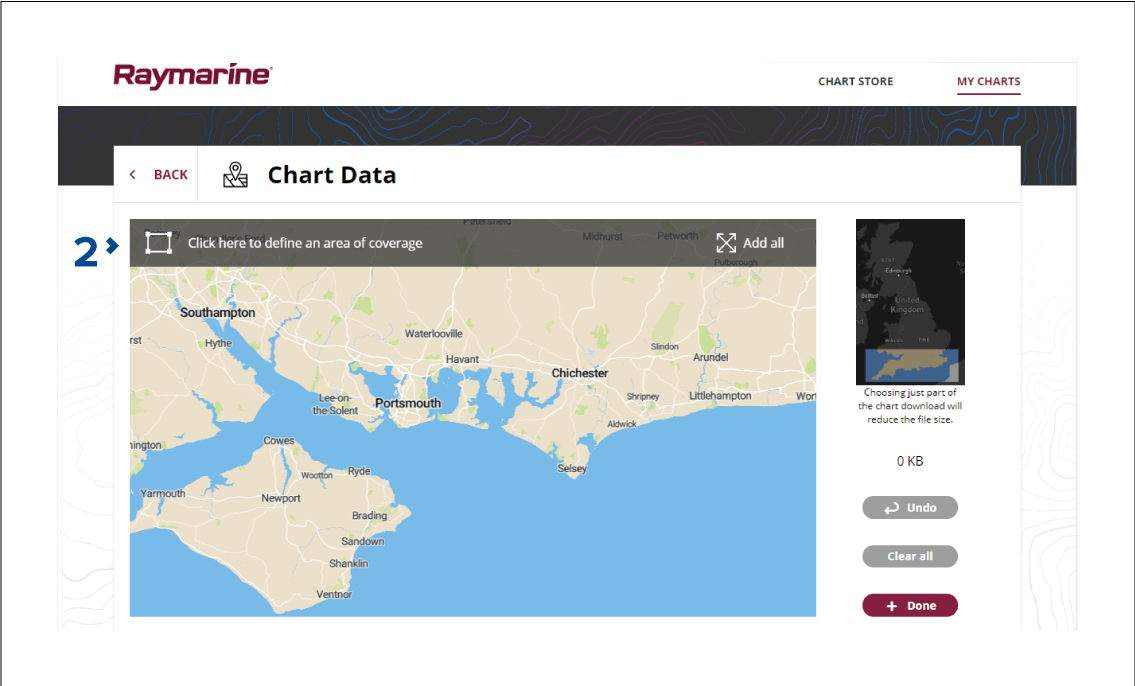
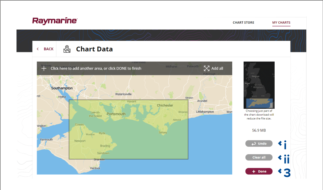
Content selection
|
Note:
The SD card must have been previously inserted into a Raymarine Axiom display. |
Note:
|
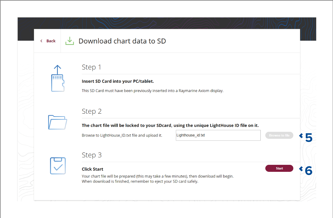
Chart modes
To change Chart mode select the required mode from the app menu.

|
In Simple mode, chart detail is suppressed to provide a clearer, simpler view for navigation and only navigation related menu options are available. Settings changes are not saved. |

|
Detailed is the default mode. Full chart detail and menu options are available. Settings changes are saved to the user profile in use. |

|
Fishing mode optimizes the Chart app for Fishing and if supported by your selected cartography, displays more detailed contour lines. Full menu options are available. Settings changes are saved to the user profile in use. |

|
Weather mode is available when the MFD is connected to a compatible Weather receiver (SR150). Weather mode allows you to overlay weather data directly on the chart and view animated weather graphics or read weather reports. Only Weather related menu options are available. Settings changes are saved to the user profile in use. For further details on Weather mode refer to: Weather mode |
|
In Tides mode, Tide Station and Current Station icons are replaced with graphics representing Tide and Current conditions. Animation controls are displayed that enable playback of Tide and Current predictions over a 24 hour period. Tides mode also suppresses chart detail, to enhance the Tide and Current graphics and enables own vessel Tide vector graphics. |
|
Racing mode optimizes the Chart app for Race Sailing. Racing mode is available when the MFD is setup with Sailing as the boat activity. In Racing mode, Race Start Line and Race Timer options become available from the menu, allowing you to create a start line and countdown timer which can help optimize your racing start. |
Vessel details
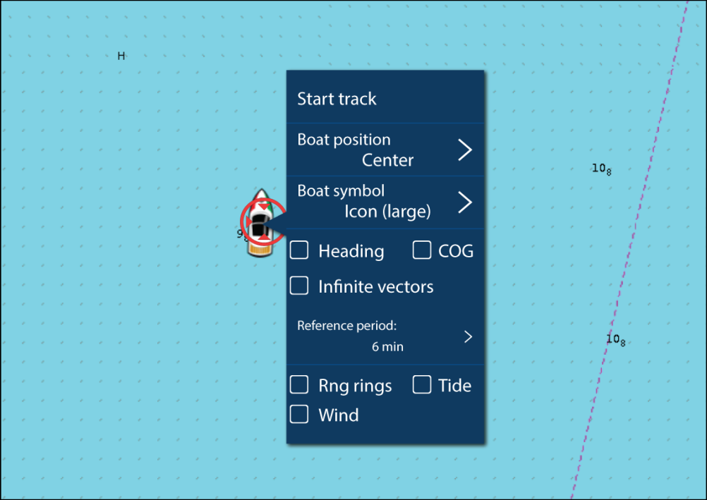
From the Vessel details pop-over you can:
- start/stop a track.
- offset the position of the vessel symbol.
- change the symbol used to represent your vessel.
- set the length of vessel vectors.
- show / hide Heading and COG vectors.
- show / hide Range Rings.
- show / hide Tide and Wind graphics.
|
Note:
In Simple mode, the only option available is Start/stop track. |
Object selection and information
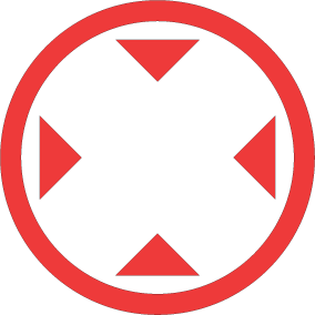
Cursor info boxes enabled
If the Cursor info box setting is enabled then when an object is selected an information pop-up is displayed. Selecting the pop-up will display a full screen information page.
The Cursor info boxes setting is accessed from the Advanced setting tab:
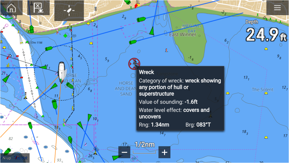
Full chart information
Selecting and holding on the object will display the object context menu.
Selecting Chart info will display the chart information page.
Layers
View and motion
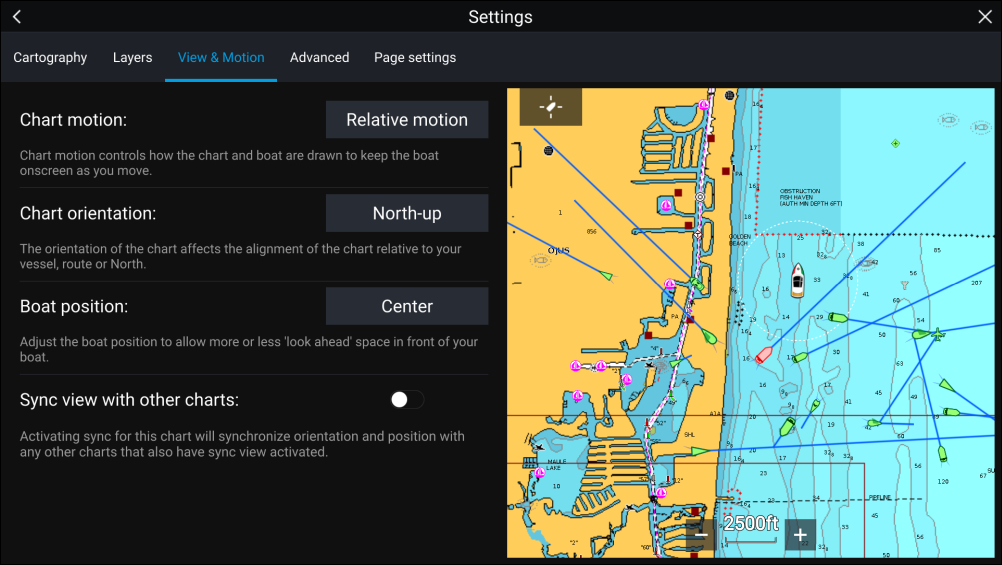
Chart motion
Chart motion controls how the chart and boat are drawn to keep the boat onscreen as you move.
Chart orientation
The orientation of the chart affects the alignment of the chart relative to your vessel, route or North.
Boat position
Adjust the boat position to allow more or less ‘look ahead’ space in front of your boat.
Sync view with other charts
Synchronize the orientation and position of all charts that have this setting enabled.
Camera tracking
2 options are available for camera tracking:
Camera tracking options are available from the Context menu in the Chart and Radar apps: , or .
Automatic tracking
You can use the Camera app settings to configure automatic tracking for AIS, Radar and MoB targets:
Navigation
Navigating to a waypoint or point of interest
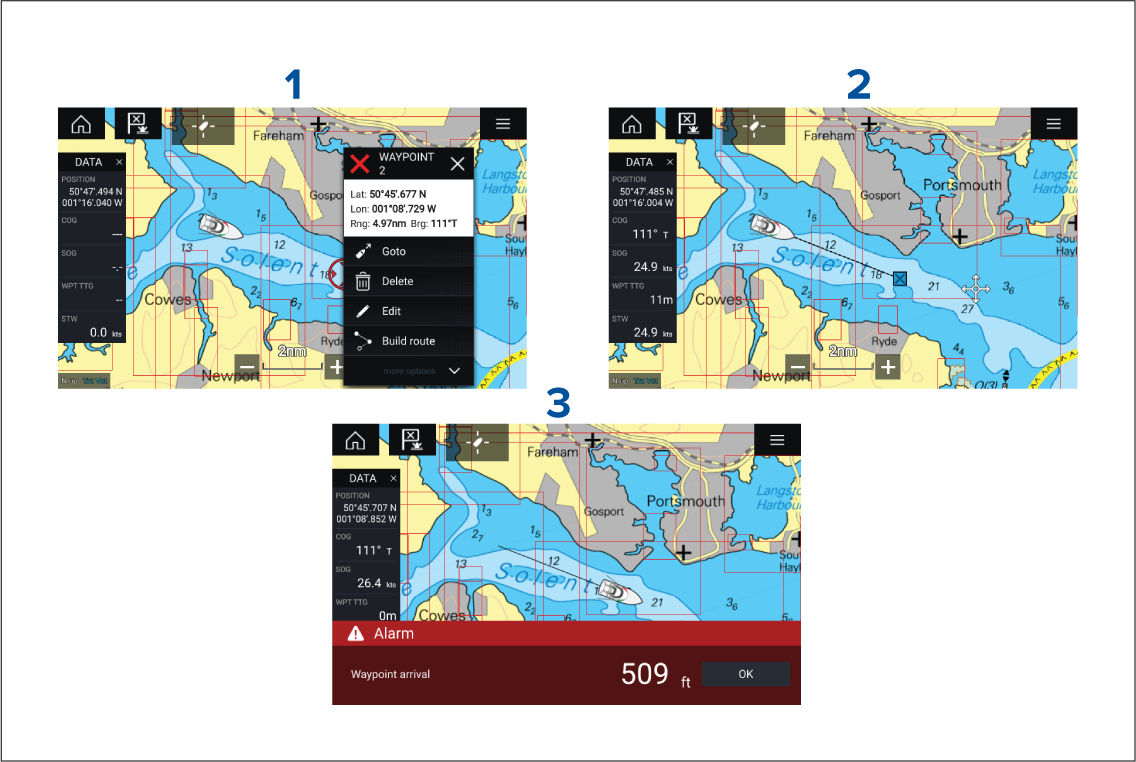
You can also perform a Goto from the Go menu: or .
For more information on waypoints and waypoint management refer to: Waypoints, Routes and Tracks
Restarting cross track error (XTE)
SAR (Search and Rescue) Patterns
SAR Patterns are routes that can help you find an object in the water. The pattern can be modified and can take the effects of the tide into account, providing a more accurate and consistent route to search. SAR Patterns can be created on your MFD in the Chart app.

Access search pattern options: .
The available Search Patterns are:
- Sector Search
- Creeping line
- Parallel Line
Once a search pattern is created it is saved as a Route and can be managed and navigated in the same manner as any other saved Route. For more information refer to: Routes
Sector search pattern
| Note: As the Search patterns take in to account drift, the resulting Route may not resemble the patterns shown. |
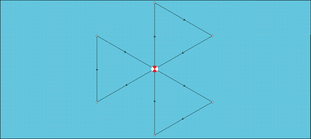
Creating a sector search pattern
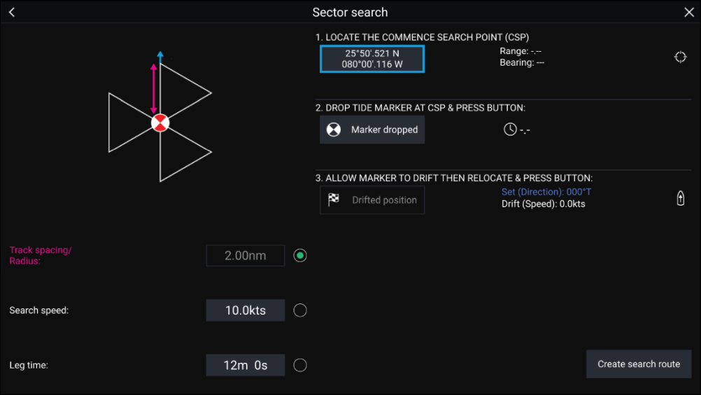
|
Variable |
Maximum Value |
|---|---|
|
Track spacing / Radius |
5 nm / 5 sm / 5 Km |
|
Search Speed |
40 Kts / 46 Mph / 74 Kph |
|
Leg Time |
59m 59s |
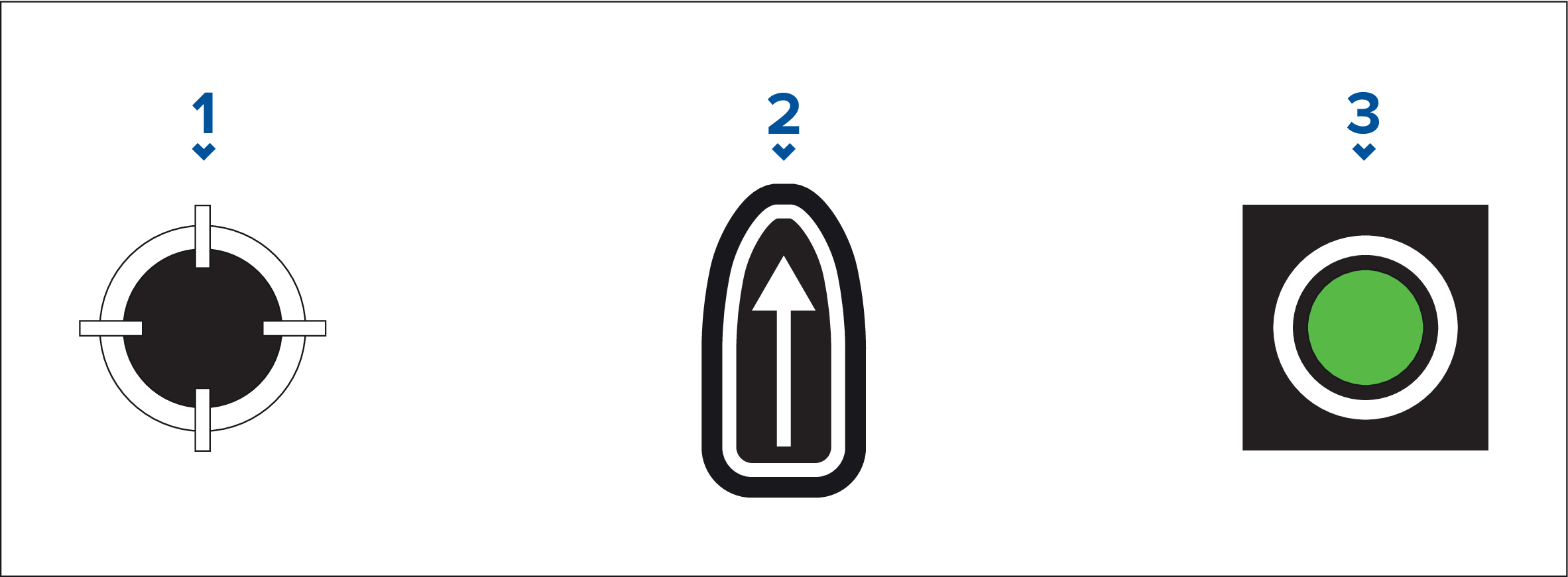
- CSP Shortcut
- Set / Drift Shortcut
- Output
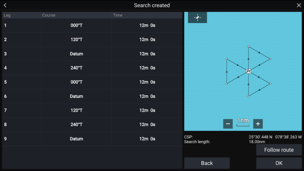
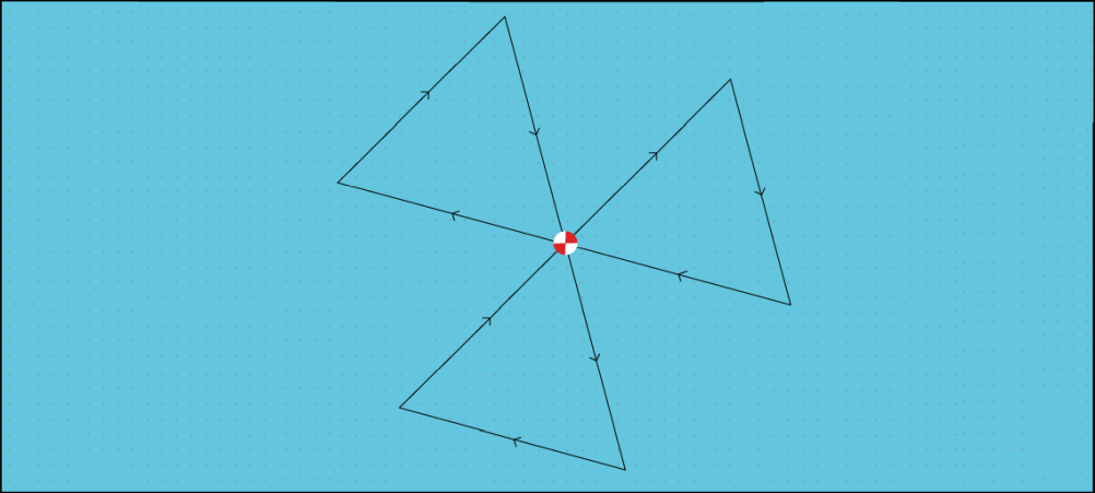
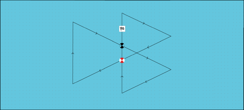
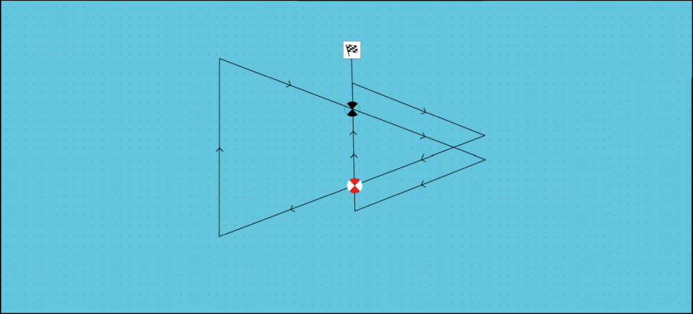
Expanding square search pattern
|
Note:
The Search patterns take drift into account, and therefore the resulting route may not resemble the patterns shown. |
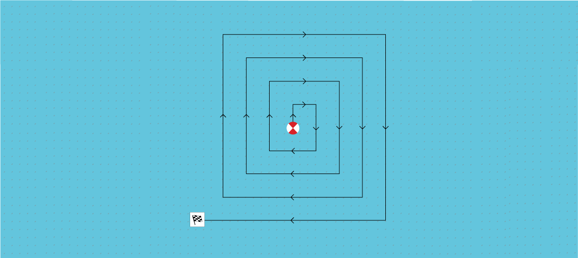
Creating an expanding square search pattern
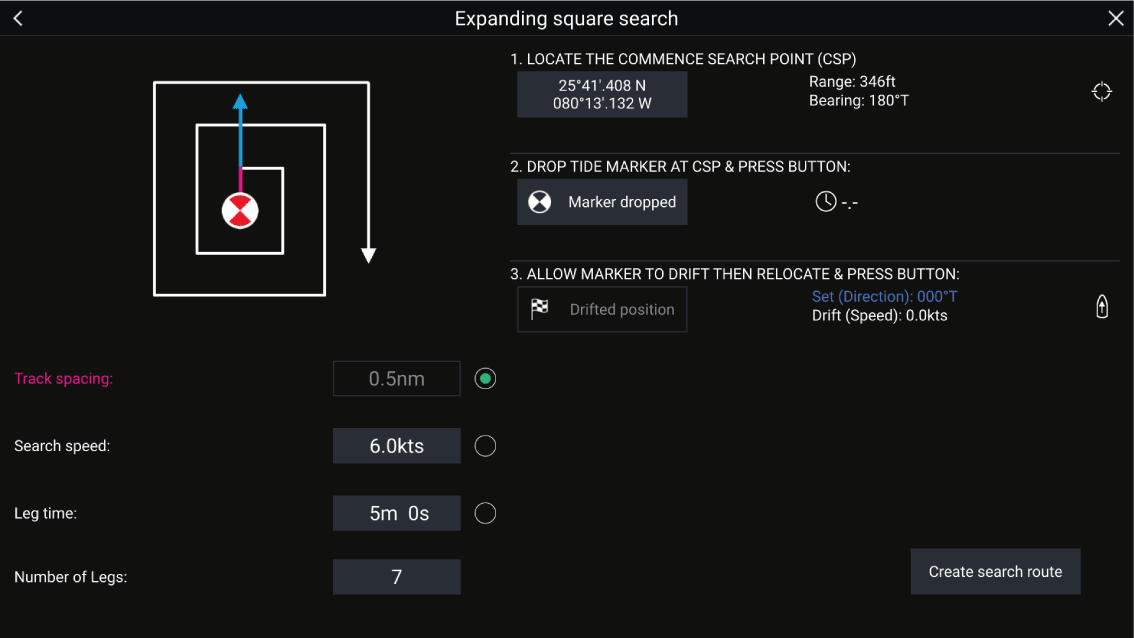
|
Variable |
Maximum Value |
|---|---|
|
Track spacing / Radius |
5 nm / 5 sm / 5 Km |
|
Search Speed |
40 Kts / 46 Mph / 74 Kph |
|
Leg Time |
59m 59s |
- CSP Shortcut
- Set / Drift Shortcut
- Output
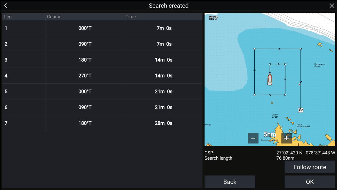
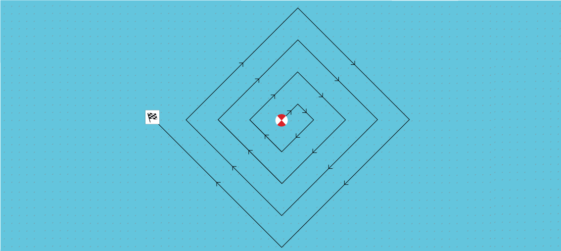
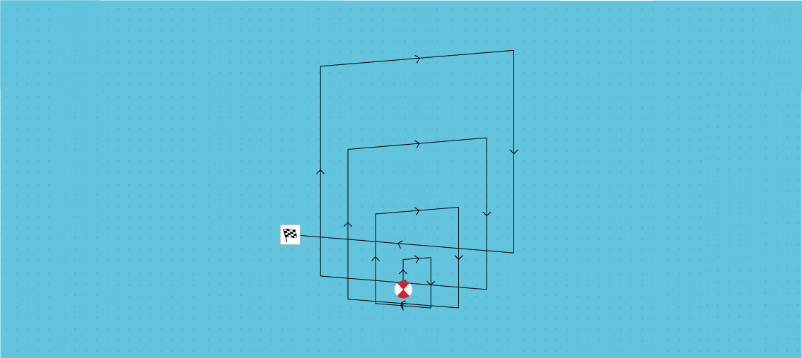
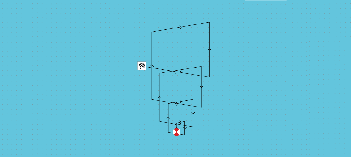
Creeping line / Parallel line search pattern
The Creeping Line search should be used when there is a logical end of the search area to start your search from.
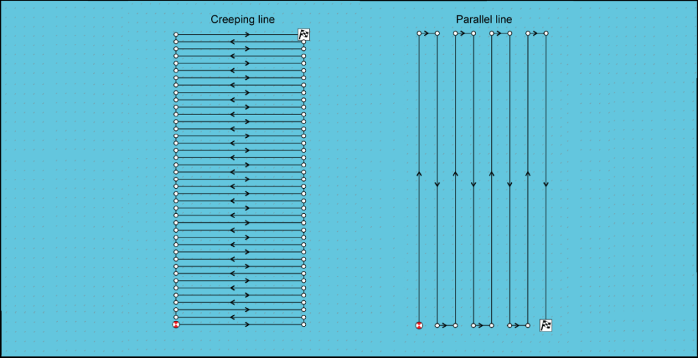
Creating a Creeping line / Parallel line search pattern
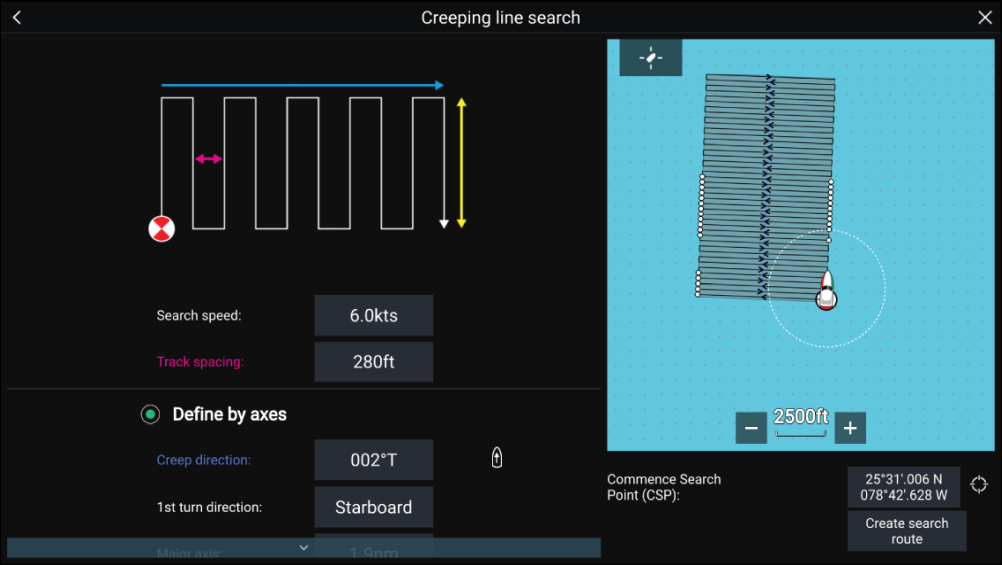
|
Variable |
Maximum Value |
|---|---|
|
Track spacing / Radius |
5 nm / 5 sm / 5 Km |
|
Search Speed |
40 Kts / 46 Mph / 74 Kph |
|
Major / Minor Axis |
20 nm / 23 sm / 37 Km |
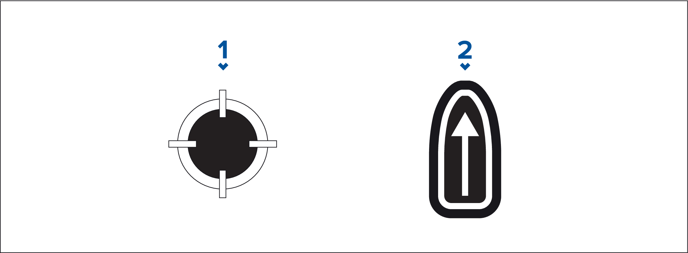
- CSP Shortcut
- Creep / Parallel Direction Shortcut
Note:
|
Laylines
When a layline is used to calculate the route to a waypoint, it will take into account a number of factors to provide a better alternative course, compared to simply navigating in a straight line to a waypoint.
The reason why laylines are a more efficient way to sail to a specific point is because they’re based on True Wind Direction (TWD) and either: a) fixed upwind / downwind sailing angles, or b) the use of polars to reflect the performance of your particular vessel. In this respect, sailing along laylines maximizes your Velocity Made Good (VMG) to windward. Another reason why laylines are more accurate is because they can also be configured to account for tidal current, as well as the leeway of your vessel.
To ensure the layline calculations are as accurate as possible, it’s important to ensure that the following settings are correctly configured:
- Boat details (specifically those relating to sailing):
- Laylines settings:
For more information on these settings, refer to: Boat details and Laylines settings
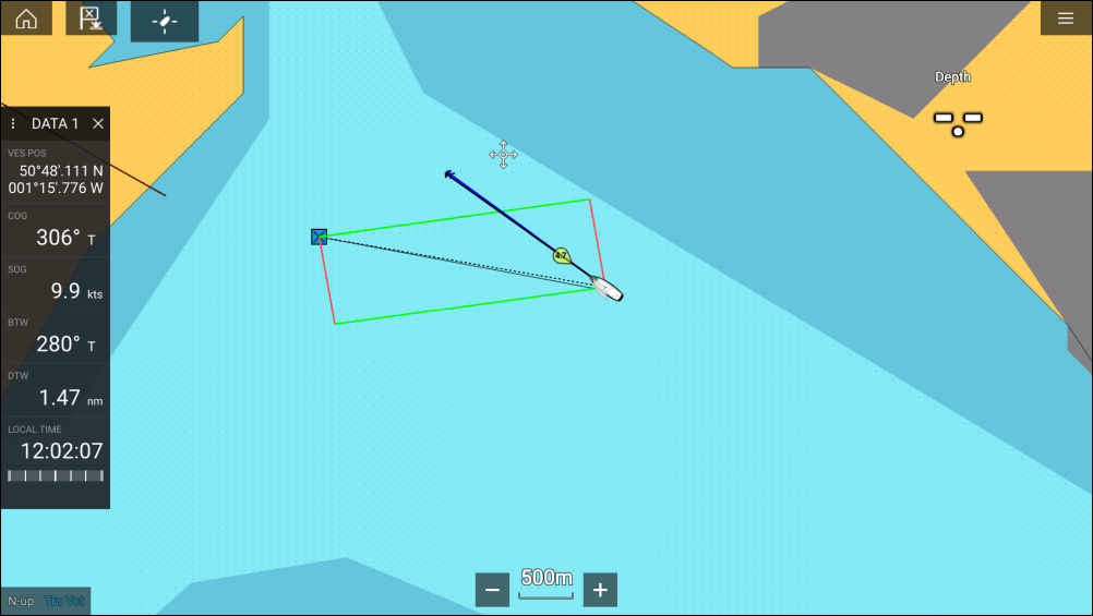
|
Note:
You should not steer your vessel so that its heading points exactly along the layline. Instead try to align your Course Over Ground (COG) with the visual laylines, as well as using the information displayed on the Sailing page in the Dashboard app to help you steer to your optimum wind angle. Your vessel should then travel along the layline, under the effects of tide and leeway. |
Sailing data page
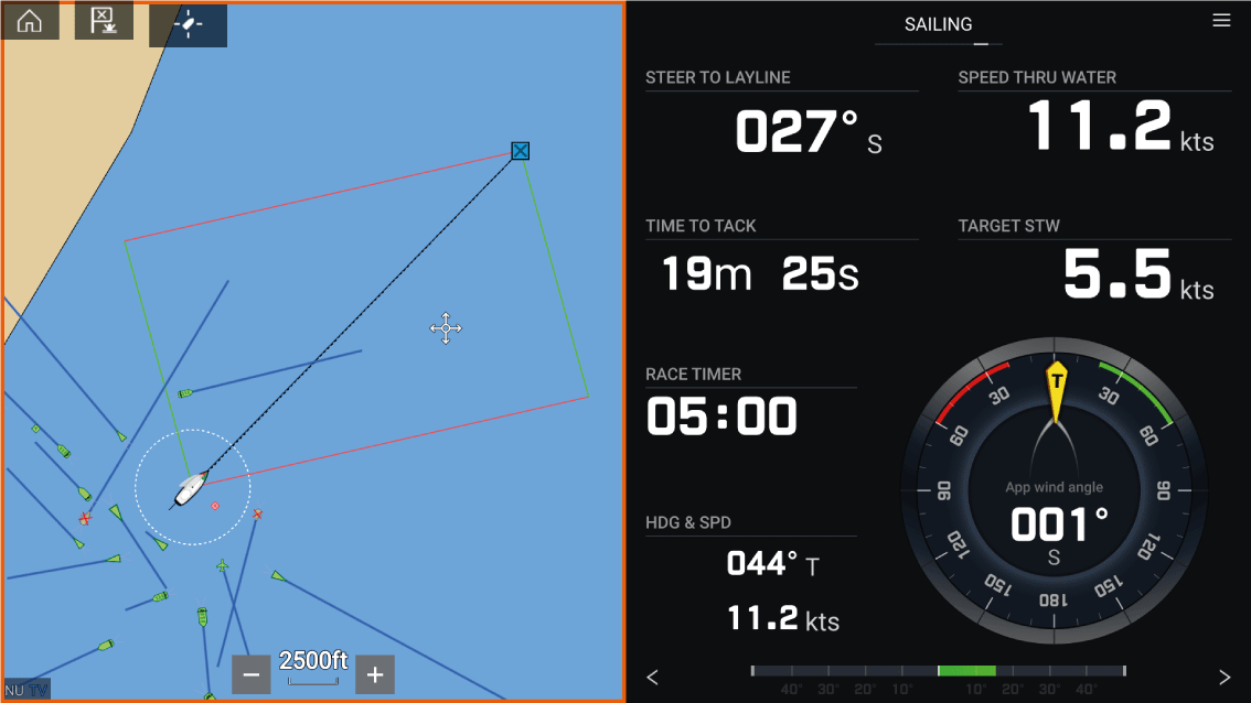
Sailing dials can be displayed in the Dashboard app by selecting the Sailing default data page. For more information on customizing the Sailing data page, refer to Dashboard app
Laylines — system requirements
- Your MFD must be running LightHouse ™ software version 3.9 or later.
- The Boating Activity setting must be set to Sailing during the MFD Startup Wizard procedure. For more information on how to configure the Boating Activity settings, refer to: Getting started
-
The following data must be present on the MFD network:
- Wind
- Speed Through Water (STW)
- GPS
- Heading
Enabling Laylines

Laylines settings
|
Setting |
Description |
Options |
|---|---|---|
|
Sail Performance |
Allows you to select a profile that determines the preferred level of sailing performance when using laylines. The laylines feature is only available when the profile is set to Fixed Angles or Polars.
|
|
|
(Fixed angle) Upwind angle |
|
|
|
(Fixed angle) Downwind angle |
|
|
|
(Polar) Polar |
|
|
|
Display Layines on this chart |
|
|
|
Adjust for tides |
|
|
|
Boat type |
|
|
|
Show wind shifts |
|
|
|
(Wind shifts) Time Period |
|
|
|
(Wind shifts) Reset |
|
|
Displaying and interpreting laylines
Laylines are displayed as a parallelogram under the following conditions:
- The vessel is under active navigation towards a Waypoint or Goto.
- A tack is required to meet an active Waypoint or Goto.
- The direct distance to the destination point is less than 150 nm from your vessel.
When the destination point is upwind the laylines will be displayed in a parallelogram formation, with green and red laylines showing the port and starboard tacks, as shown below:
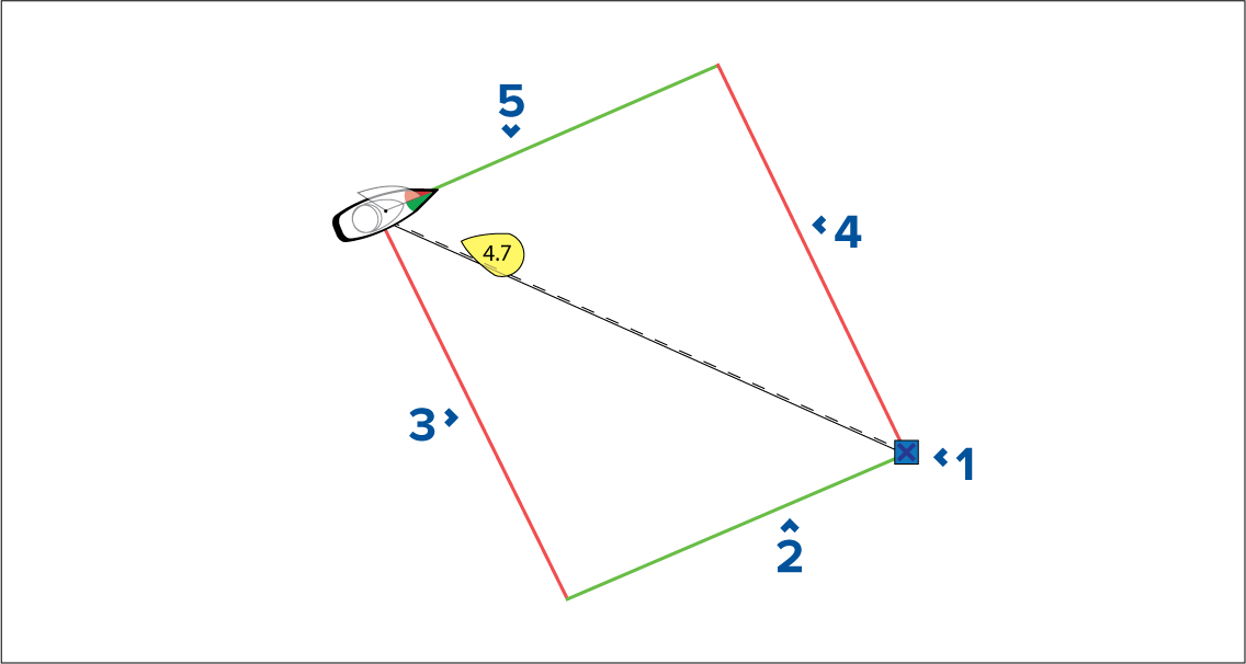
- Destination
- Starboard destination layline
- Port vessel layline
- Port destination layline
- Starboard vessel layline
When the destination point is downwind the laylines will be displayed as an orange parallelogram formation, adjusted for gybing, as shown below:
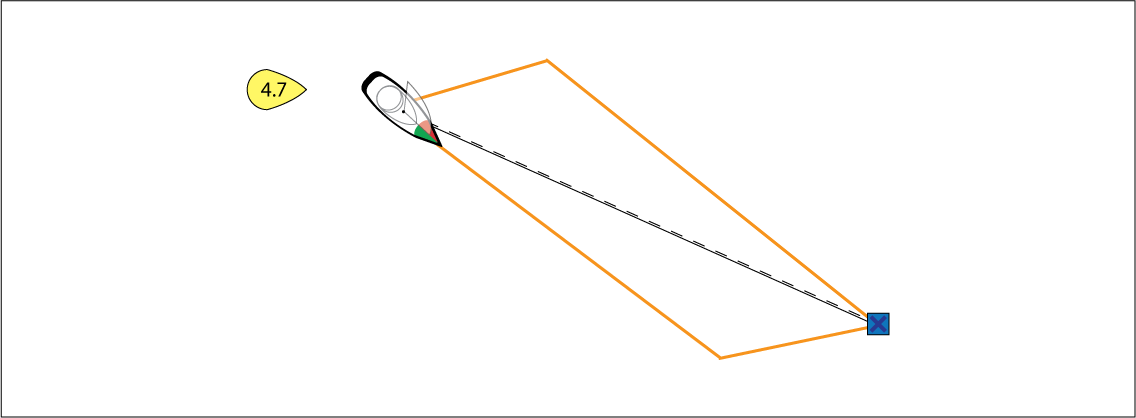
Displaying wind shift data
- With TWD holding at the high end of its range of variation, the vessel can tack to starboard and will lay the windward or leeward mark as it enters the shaded area. However, if TWD shifts back towards the lower end of its range of variation, the vessel will fall short of the layline and may have to perform extra tacks to reach the waypoint.
- With TWD holding at the low end of its range of variation, the vessel can tack to starboard and will only lay the windward or leeward mark when it reaches the end of the shaded area. However, if TWD shifts back towards the high end of its range of variation, the vessel will overstand the windward or leeward mark and may need to travel farther to reach the waypoint.
- Depending on the situation, the normal course of action would be to tack when the vessel is halfway through the shaded area. However this may not be the shortest or quickest route.
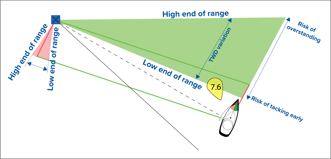
Wind shift data options are available from the Laylines settings page:
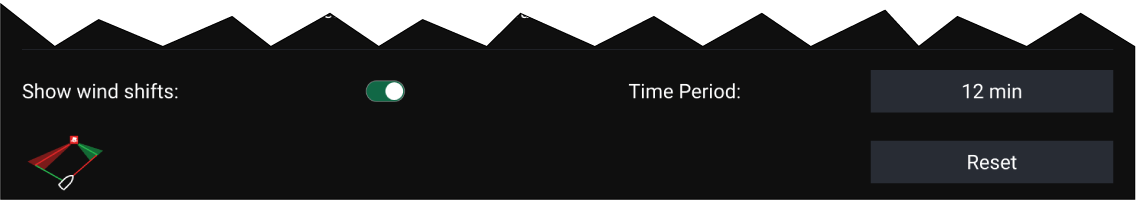
- Show wind shifts — Toggle wind shifts ON / OFF
- Time Period — Select the time period that you want the wind shift data to cover
- Reset — Reset the recorded wind shift data
Race Start Line (SmartStart) and Race Timer
The basic concept of an effective race start is to guide your vessel and tune the sail configuration in an optimum way to ensure you are approaching the start line at the very last moment with full power. In race sailing, the countdown to this last moment is known as “Time to Burn”.
The race start line features help you to do this by providing a visual indication of the position of the race line on the Chart, as well as key data, including race timer, distance to start line, line bias, and Time to Burn. These features can also be used in conjunction with Laylines to further assist you in optimizing your approach to the start line. When the Race Start Line, Race Timer and Laylines are active, Laylines will visually protrude from the race start line’s port and starboard ends to help guide your vessel on an optimum course to the start line.
For more information on Laylines, refer to: Laylines
The Race Start Line and Race Timer data is displayed in 2 different places:
- In the Chart app’s Sidebar — When the Chart app is in Racing mode, you can swipe from the left of the screen to display a sidebar showing the key race start information.
- In the Dashboard app — The dedicated Race Start page displays key race start information, including an apparent wind sailing dial, race timer, distance to start line, line bias, Time to Burn, and more. For more information, refer to: Race Start data items
Note:
|
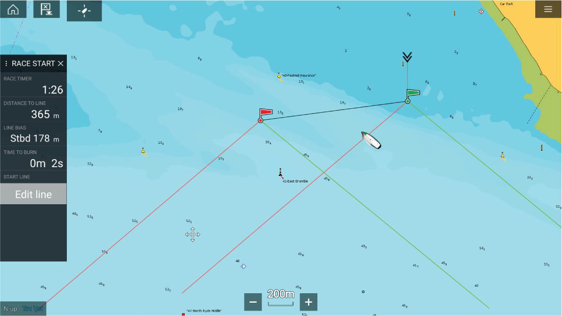
Creating the Race Start Line
The end points can be created by:
- Placing them anywhere on the Chart app — or for greater accuracy — placing them using existing chart waypoints and chart objects (e.g. Buoys).
- Pinging your vessel’s current location, using GPS position data.
Once both end points have been entered, the race start line will be drawn between the two points.
Placing the Race Start Line
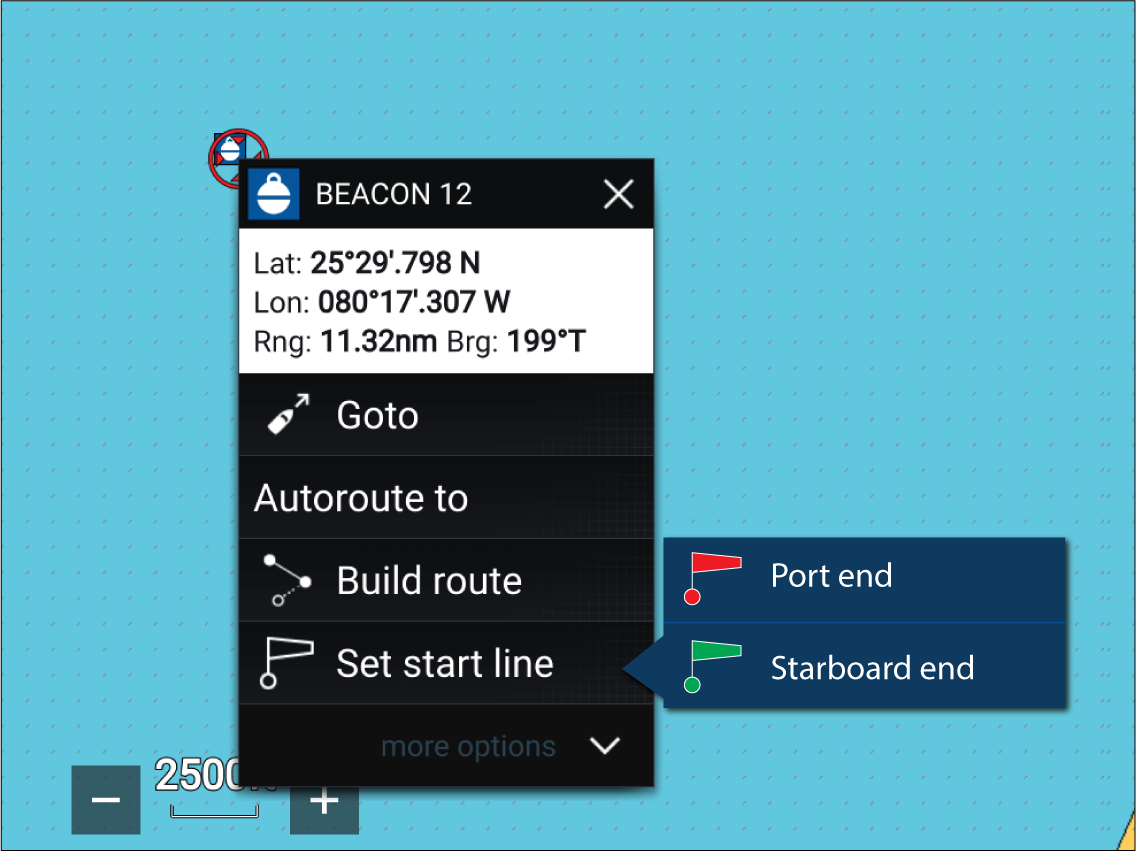
Pinging the Race Start Line
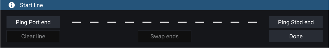
|
Important:
Pinging the Race Start Line ends will use your GPS location (from an internal or external GPS receiver). When pinging the end points, it is important to compensate for the distance between your vessel’s bow and the GPS location. |
To increase the accuracy of start line placement:
- Approach an end point from the same direction you will be traveling when starting the race.
- Align your vessel so it is perpendicular to the end point.
- When the bow of your vessel reaches the end point, ping the location.
- Repeat for the alternate end, ensuring your vessel remains perpendicular to the line.
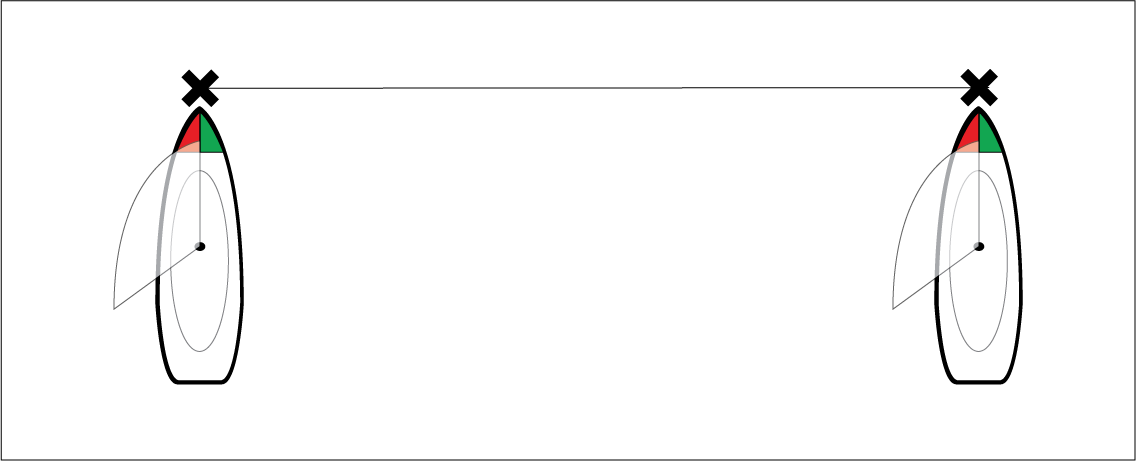
Editing and clearing the Race Start Line
Starting the Race Timer
| Note: The Race Timer can be set from 1 minute to 30 minutes. |
|
Note:
The Race Timer can also be operated from the Dashboard app Race Start Page. |
Race laylines
The start line will appear differently depending on whether it is an upwind or downwind start:
- Upwind starts will show red and green laylines as well as a Favoured End Marker on the end point closer to the True Wind Direction (TWD).
- Downwind starts will show orange laylines as well as a Favoured End Marker on the end point farther from the True Wind Direction (TWD).
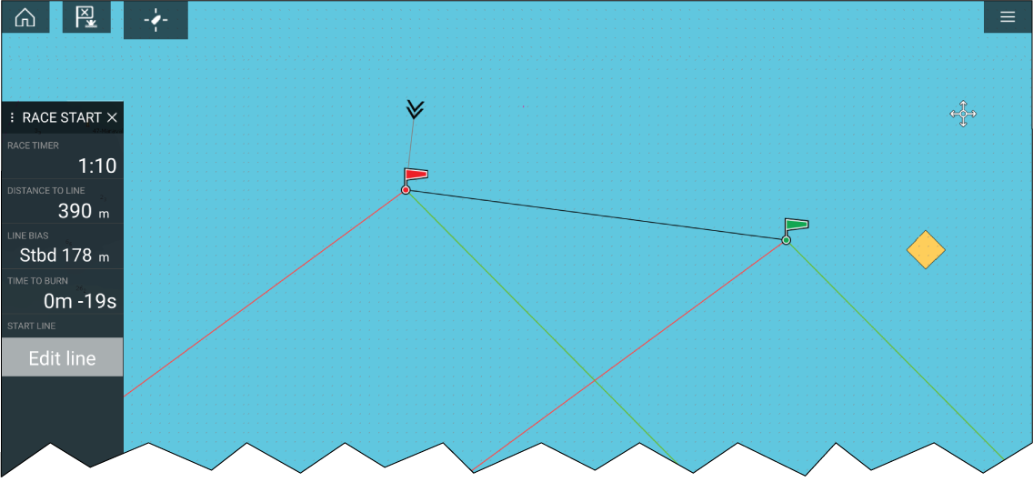
Race sidebar
|
Menu item |
Description |
Options |
|---|---|---|
|
Race Timer |
Displays the countdown time until race start. When the timer reaches 0 it will begin to count up, indicating how long it has been since race start. |
Before Start
During Countdown
When Counting Up
|
|
Distance To Line |
Displays how far your vessel is from any point of the start line. |
N/A |
|
Line Bias |
Displays how much closer or further away the favoured endpoint is to the wind in comparison to the other endpoint. |
N/A |
|
Time To Burn |
Displays how much time you have before you need to navigate towards the start line. A negative value is shown if you are predicted to be running behind and will not be at the start line at race start. Time to burn is calculated using wind speed and speed through water (STW):
For more information on sail performance refer to Laylines settings |
N/A |
|
Edit Line |
Allows you to edit the end points of the start line or clear it. You can ping the port or starboard end points to your current location as well as swap them. |
|
Dashboard
Target tracking
When targets are being tracked they appear in the AIS or Radar targets list.
The target lists can be accessed by selecting Targets from the app menu: , and then selecting the relevant tab.
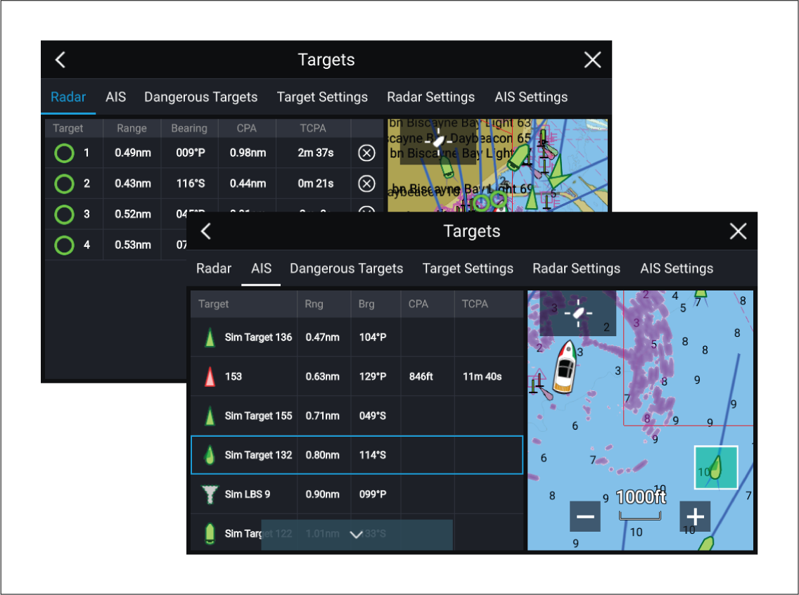
Selecting a target from the list highlights the selected target in the LiveView app pane on the right of the page.
The list identifies: Target name, Range from your vessel, and Bearing. Where relevant, CPA (Closest point of approach) and TCPA (Time to Closest Point of Approach) values will also be displayed.
AIS list
The AIS target list displays pop-over options which enable you to View full target data or add a target as an AIS buddy by selecting Add as buddy.
The Buddy feature enables you to add AIS-equipped friends and regular contacts to a “Buddy List” on your MFD. As soon as a vessel on your Buddy List comes within range of your AIS receiver, the onscreen vessel icon changes to indicate this.
AIS icons used for targets marked as buddies will be filled yellow. You can also rename buddy targets or remove targets from your buddy list.
Radar list
The Radar target list can be Sorted By: target Number or its Range from your vessel.
Radar targets can be cancelled individually by selecting the ‘X’ next to the target’s details in the list, or you can cancel all targets by selecting Cancel all targets.
You can display Radar target information onscreen by selecting Target info from the Radar target pop-over options.
Target vectors
Target vectors settings can be accessed from the Target Settings tab: .
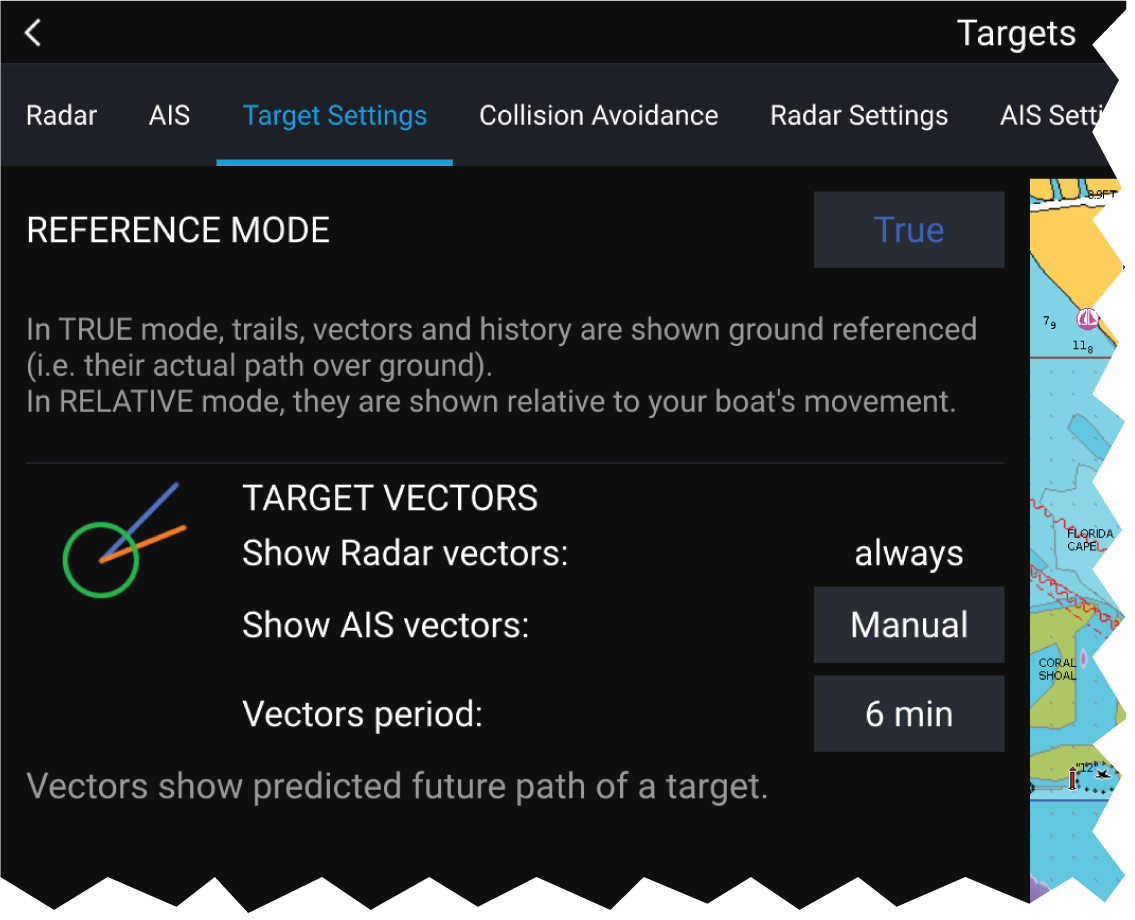
The vectors can be set to True or Relative.
The Vector length identifies where the target will be after the specified time has passed. You can adjust the length of the vector by selecting a time from the Vector length pop-over options.
AIS vectors can be set to All (displayed for all targets) or Manual (only displayed when enabled using the target’s context menu).
Target vectors can be enabled and disabled for individual targets: Press and hold on an AIS target to display the context menu, and then select Vector.
Dangerous targets alarm
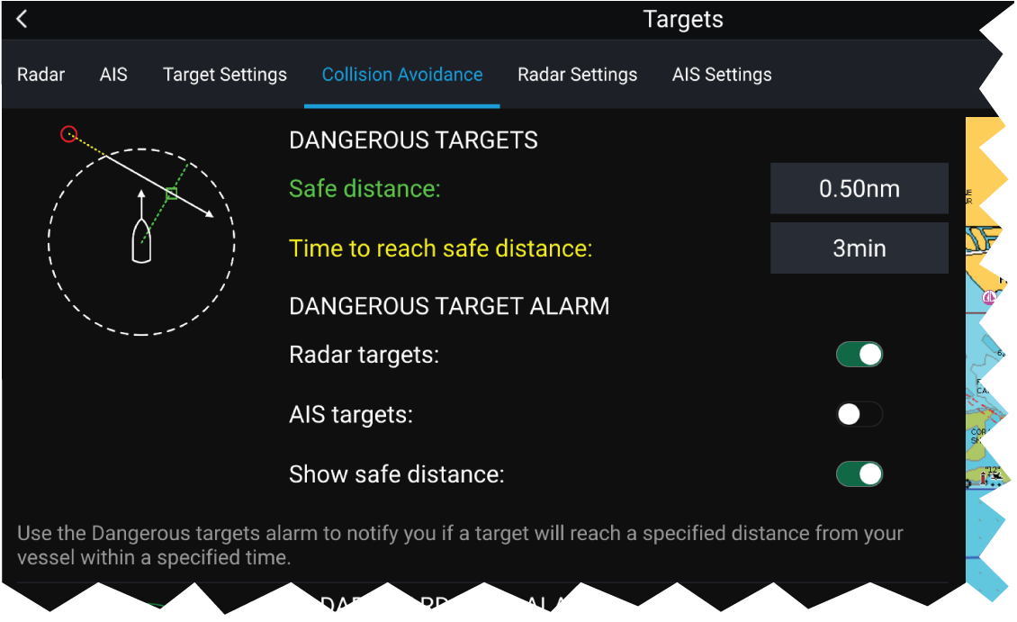
To set up the Dangerous target alarm, first adjust the Safe distance to the desired value and then select a Time to reach safe distance. The alarm will be triggered if a tracked target will reach the specified Safe distance from your vessel within the time period selected.
You can select whether you want the Dangerous target alarm to track Radar targets, AIS targets or both.
You can display a Safe distance ring around your vessel in the Chart and Radar app using the Show safe distance control.
Radar settings
| Setting | Description | Options |
|---|---|---|
| Radar selection |
When more than 1 Radar scanner is connected you can choose which Radar to use for the Radar layer in the Chart app. |
List of available Radar scanners |
| Transmit |
Start the Radar scanner transmitting or put it in Standby. |
|
| Dual range |
Enables and disables dual range on compatible Radar scanners |
|
| Channel |
When Dual range is active, you can switch between channels. |
|
| Show Radar overlay |
Enables and disables the Radar layer in the Chart app. |
|
| Visibility |
Determines the visibility (opacity) of the Radar layer. |
|
| Palette |
Selects the color used for the Radar layer |
|
| Show sector blanking limits |
Enables and disables radar blank sectors. For more information on blank sectors refer to Blank sectors |
|
| Use Radar without heading data |
Enables use of Radar layer when Heading data is not available. |
|
| Range |
Determines the range used for the Radar layer. |
Radar range values |
AIS settings
|
Setting |
Description |
Options |
|---|---|---|
|
Show AIS targets in Chart / Show AIS targets in Radar |
Enables and disables AIS targets in the Chart and Radar apps. |
|
|
Enables and disables the display of enhanced AIS target icons. |
|
|
|
When enabled, AIS target names are permanently displayed next to the target icon. |
|
|
|
Show these AIS types |
Determines the types of AIS target displayed in the Chart and Radar apps. |
|
|
Hide static targets |
When enabled, an AIS target travelling under 2 knots will be hidden, unless it is or becomes dangerous. |
|
|
When enabled, your vessel’s AIS device will not transmit your position or details. |
|
AIS target symbols
You can enable enhanced AIS target symbols from the Advanced Settings menu: (). With enhanced mode enabled, the enhanced symbols are used in place of the standard vessel symbols.
Standard AIS symbols — type

|
Vessel |

|
SART (Search and Rescue Transponder) |

|
Land-based station |

|
ATON |

|
SAR (Search and Rescue) |

|
Virtual ATON |
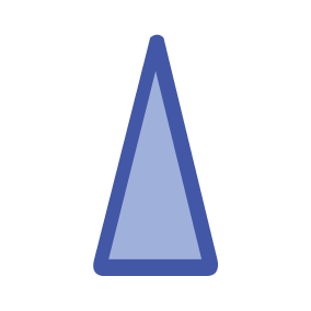
|
* Blue Force vessel |

|
* Blue Force SAR |
| Note: * Requires STEDS-AIS hardware. |
Vessels equipped with STEDS-AIS hardware appear as Blue Force targets if:
- your MFD has a valid passphrase.
- you have received a SITREP from them within the last 6 minutes.
- their AIS mode is not set to Receive only.
If the above conditions are not met then the target icon will revert to using the standard, Green AIS target icon.
Enhanced AIS symbols — type

|
Sailing Vessel |

|
Commercial |

|
High speed vessel / Wing In Ground vessel |

|
Cargo vessel |

|
Passenger vessel |
|
Other |
Enhanced AIS symbols are scaled or outlined according to the reported size of the vessel, as shown below:

|
Relative length (Grey outline) |
AIS symbol status

|
Lost (No border, crossed through) |

|
Uncertain (Dashed outline) |
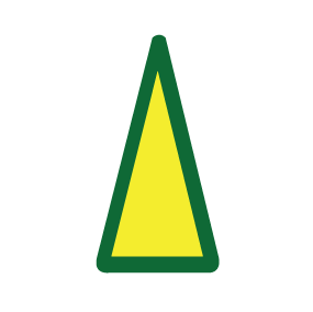
|
Buddy (Yellow fill) |

|
Dangerous and Uncertain (Dashed outline and Flashes Red) |
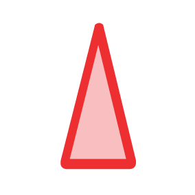
|
Dangerous (Flashes Red) |

|
ATON off position (Red border) |
Blue Force overview
The Blue Force features offer secure (encyrpted) communications and surveillance capability through the existing Automatic Identification System (AIS) network.
As these messages cannot be received by standard AIS receivers, Blue Force-equipped vessels are effectively invisible to non-Blue Force users, in terms of AIS transmissions. Blue Force users can still receive the standard AIS transmissions of other non-Blue Force vessels.
Unique AIS target icons are used onscreen to represent Blue Force participants.
Note:
|
Blue Force SITREP
Note:
|
Once responder information has been entered, other Blue Force vessels equipped with STEDS-AIS hardware using the same passphrase will display on the Chart app. Opening a Blue Force vessel’s AIS context menu will display their vessel type and SITREP status.
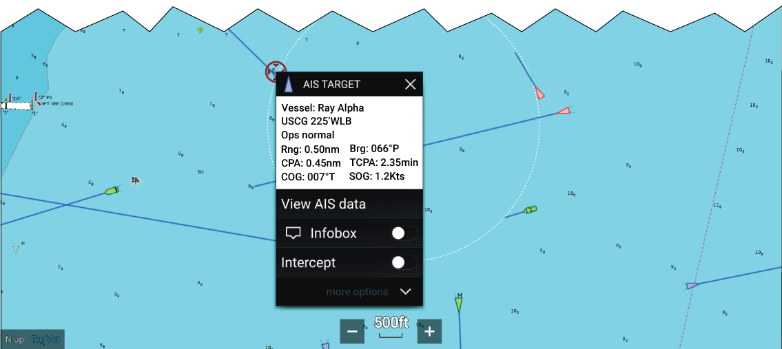
You can set your SITREP status from the Homescreen, by touching the Status Area in the top right of the Homescreen.
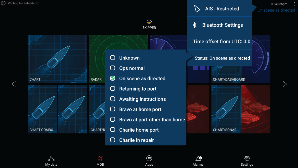
Note:
|
Collision avoidance
Additionally, Predicted Area of Danger zones are displayed to indicate where there is an increased risk of collision. The Warning line and Predicted Area of Danger zones are based on your current speed and AIS data received from targets and can help you determine whether you should change course and / or speed to avoid danger.
The Collision Avoidance graphics automatically refresh when the MFD receives new position data from the target.
| Important: The Collision Avoidance feature is a graphical aid only, provided to help increase user awareness of the potential for collision. It is vital to have a good understanding of the International Regulations for Preventing Collisions at Sea (IRPCS / COLREGS), to ensure all actions taken are in accordance with the IRPCS. Important concepts to understand in relation to Collision Avoidance include (but are not limited to): Risk assessment; Right of Way; Restricted visibility; interpreting lights and shapes; interpreting sound and light signals. In the event of conflict, the IRPCS regulations must take precedence. For more information on IRPCS / COLREGS, refer to: IRPCS |
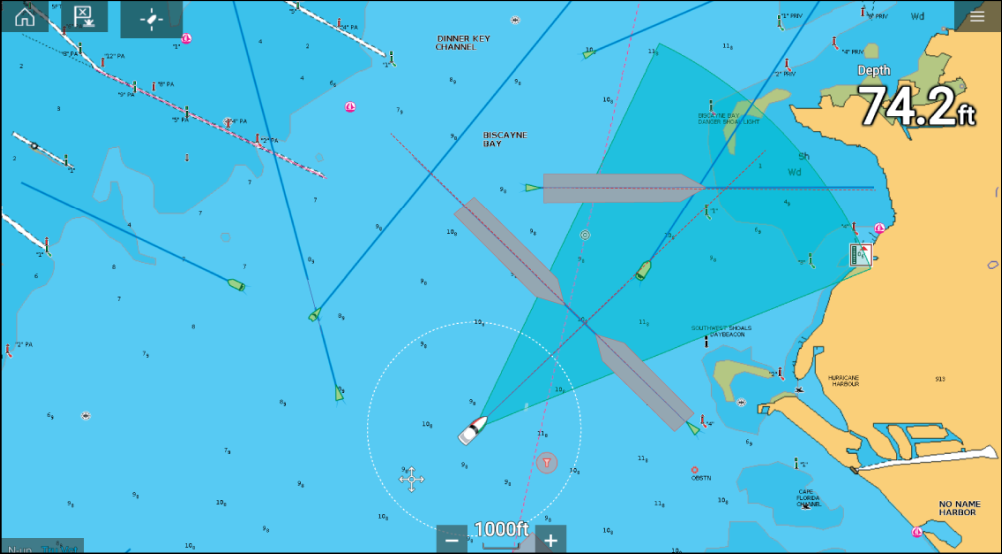
Moving Target
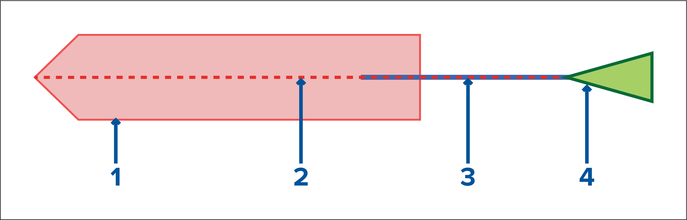
- Predicted Area of Danger zone (Predicted area based on target’s last reported position)
- Warning line
- Target COG line
- AIS Target (Last received position)
Stationary Target
(Target moving less than 2 kts)
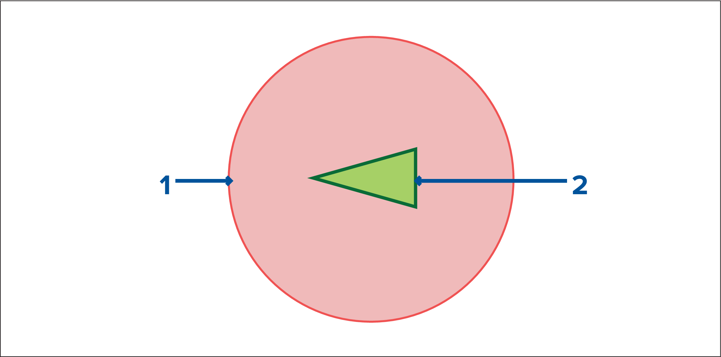
- Predicted Area of Danger zone (Predicted area based on target’s last reported position)
- Stationary AIS Target (Last received position)
Important:
You must still maintain a permanent watch for:
|
Enabling collision avoidance
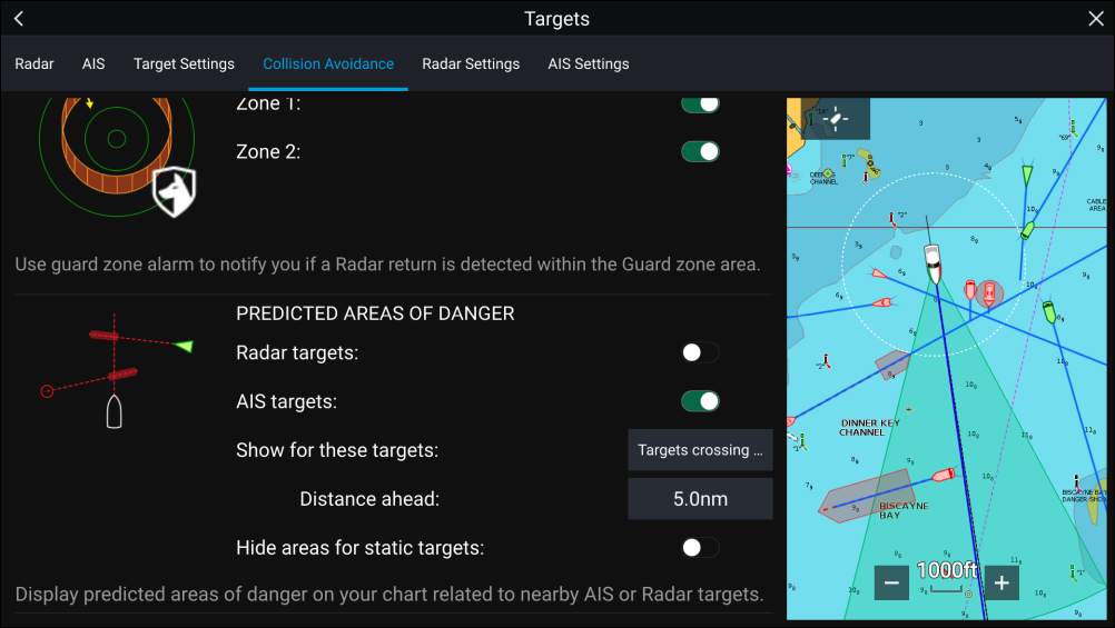
In the Collision Avoidance menu you can change the settings to determine which types of target (e.g. AIS or Radar) will have a Predicted Area of Danger zone:
|
Setting |
Description |
|---|---|
|
Radar Targets |
Enable / disable — Radar targets will have a Predicted Area of Danger zone. |
|
AIS Targets |
Enable/disable — AIS targets will have a Predicted Area of Danger zone. |
|
All targets |
Displays a Predicted Area of Danger zone on all targets in your vessel’s vicinity. |
|
Targets crossing my course |
Displays a Predicted Area of Danger zone only on targets which will potentially cross your vessel’s Interception line. |
|
Distance ahead |
Change the maximum distance of the Interception line in front of your vessel (only available with Targets crossing my course enabled).
|
|
Hide areas for static targets |
Enable/disable — Static targets (targets travelling less than 2.0 kts) will NOT have a Predicted Area of Danger zone. |
Collision scenarios
- Own vessel moving faster than target
- Target moving faster than own vessel
- Both targets moving at similar speed
Example scenario 1 — Own vessel moving faster than target vessel
| Note: These scenarios are examples provided for guidance only. |
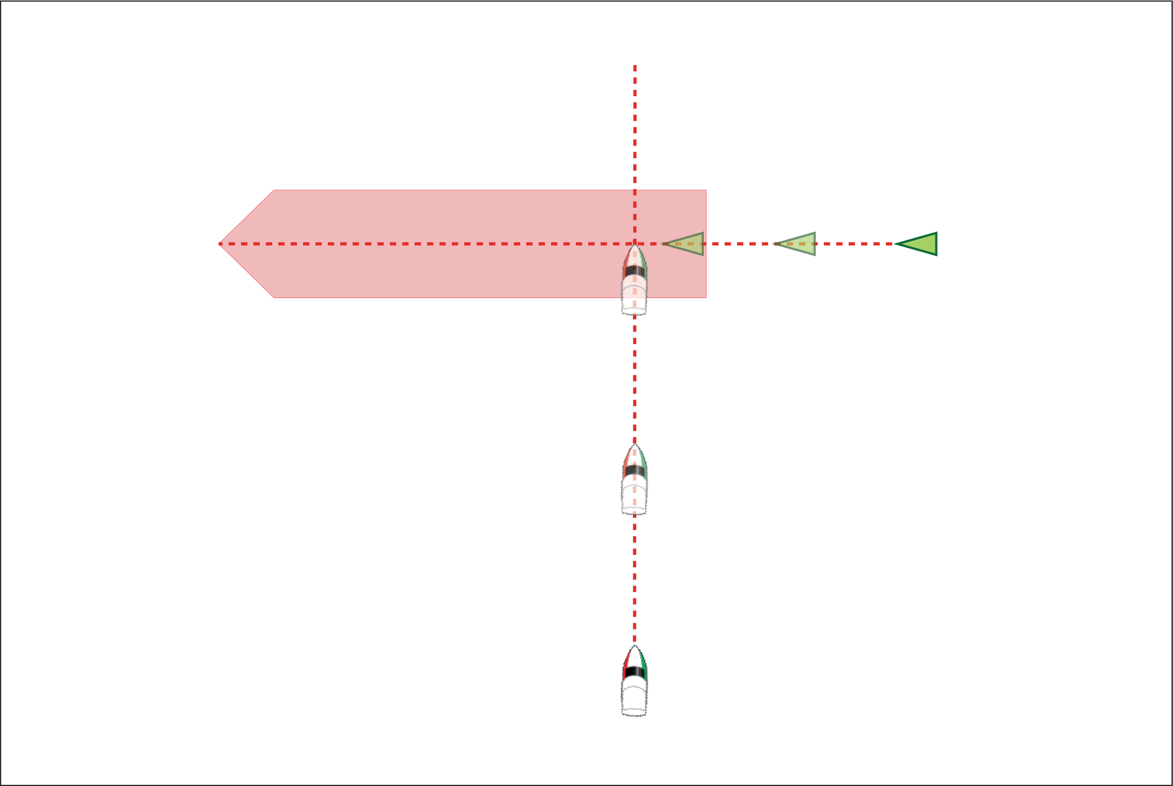
In the example above the vessel’s COG will cross with the target’s COG within the Interception zone, which could cause a collision. You should alter course and / or speed to avoid the potential collision.
Scenario 1 Course change examples
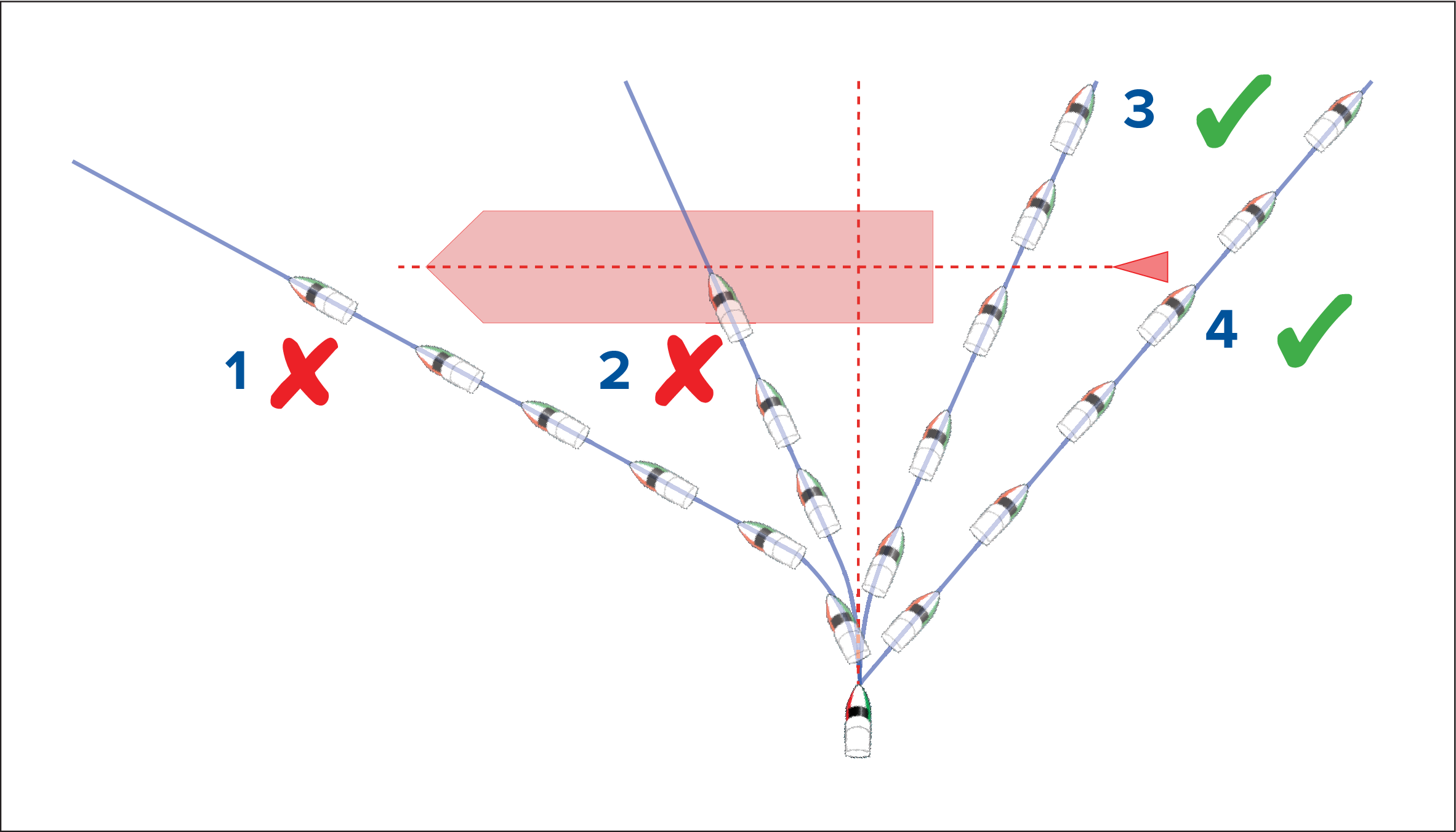
- Course alteration to pass ahead of the Interception zone [Not recommended] — Proceed with caution, there is always an inherent risk when passing in front of other vessels.
- Course alteration to pass ahead of the target vessel [Not recommended] — This manoeuvre is not recommended as your vessel will still cross through the target’s Interception zone.
- Course alteration to pass astern of the target vessel and its Interception zone — This manoeuvre alters your vessel’s course so that it does not come into contact with the target’s Interception zone and passes astern of the target.
- Course alteration to pass clear astern of the target vessel and its Interception zone. This is the preferred manoeuvre as it correctly alters your vessel’s course so that it is clear of the target’s Interception zone and passes safely astern of the target. This manoeuvre also clearly indicates to the target vessel your actual change of course.
Figure 2. Scenario 1 Speed change examples
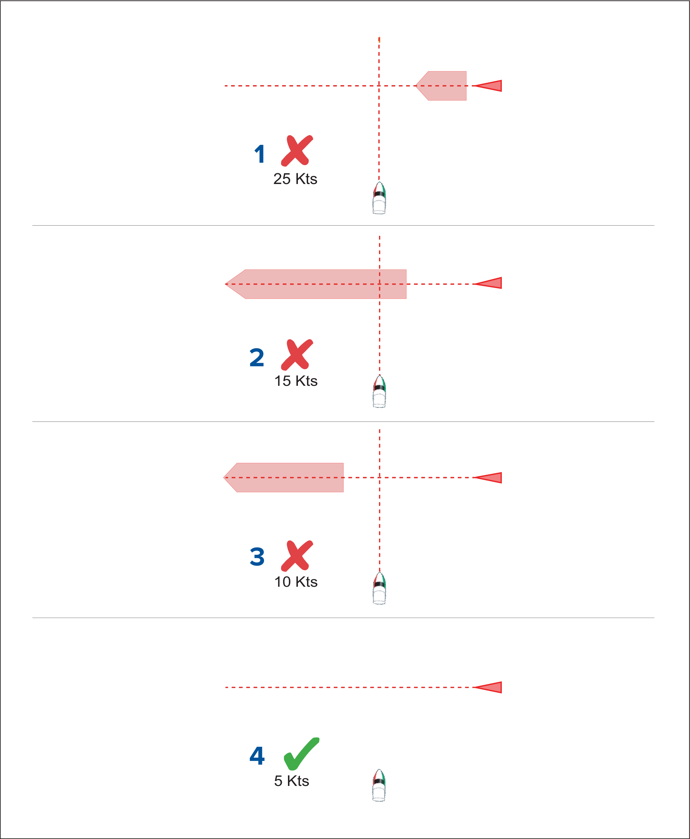
- (1) Speeding up [Not recommended] — Increasing vessel speed to pass ahead of the target vessel. Proceed with caution, there is always an inherent risk when passing in front of other vessels.
- No speed change [Not recommended] — Not changing speed or course is not an option as it can result in a collision.
- Slowing down [Not recommended] — Slowing down a sufficient amount will allow the target vessel to pass ahead of your vessel.
- (2) Slowing down — Slowing down more than a sufficient amount will allow the target vessel to pass safely ahead of your vessel.
Note:
|
Example scenario 2 — Target vessel moving faster than your vessel
| Note: These scenarios are examples provided for guidance only. |
In certain situations, when the target vessel is travelling faster than your vessel, there may be more than one opportunity for your paths to cross within the Intercept distance. If this is the case then a second Interception zone is displayed.
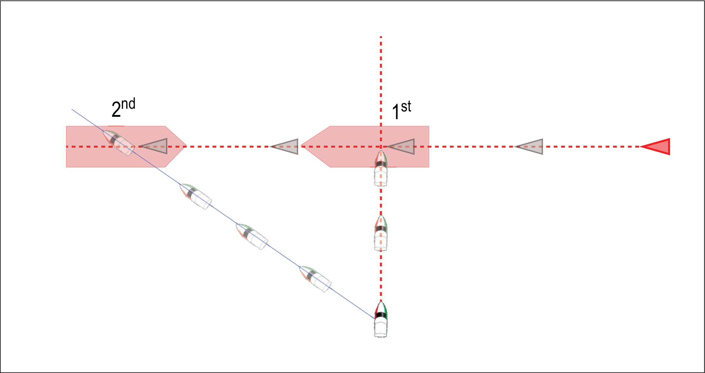
- 1st — The first Interception zone (displayed closest to the target vessel) represents a bow-to-bow collision.
- 2nd — The second Interception zone (displayed farthest from the target vessel) represents the target vessel running you down from behind.
When altering course and speed, both Interception zones must be avoided.
Scenario 2 Course change examples
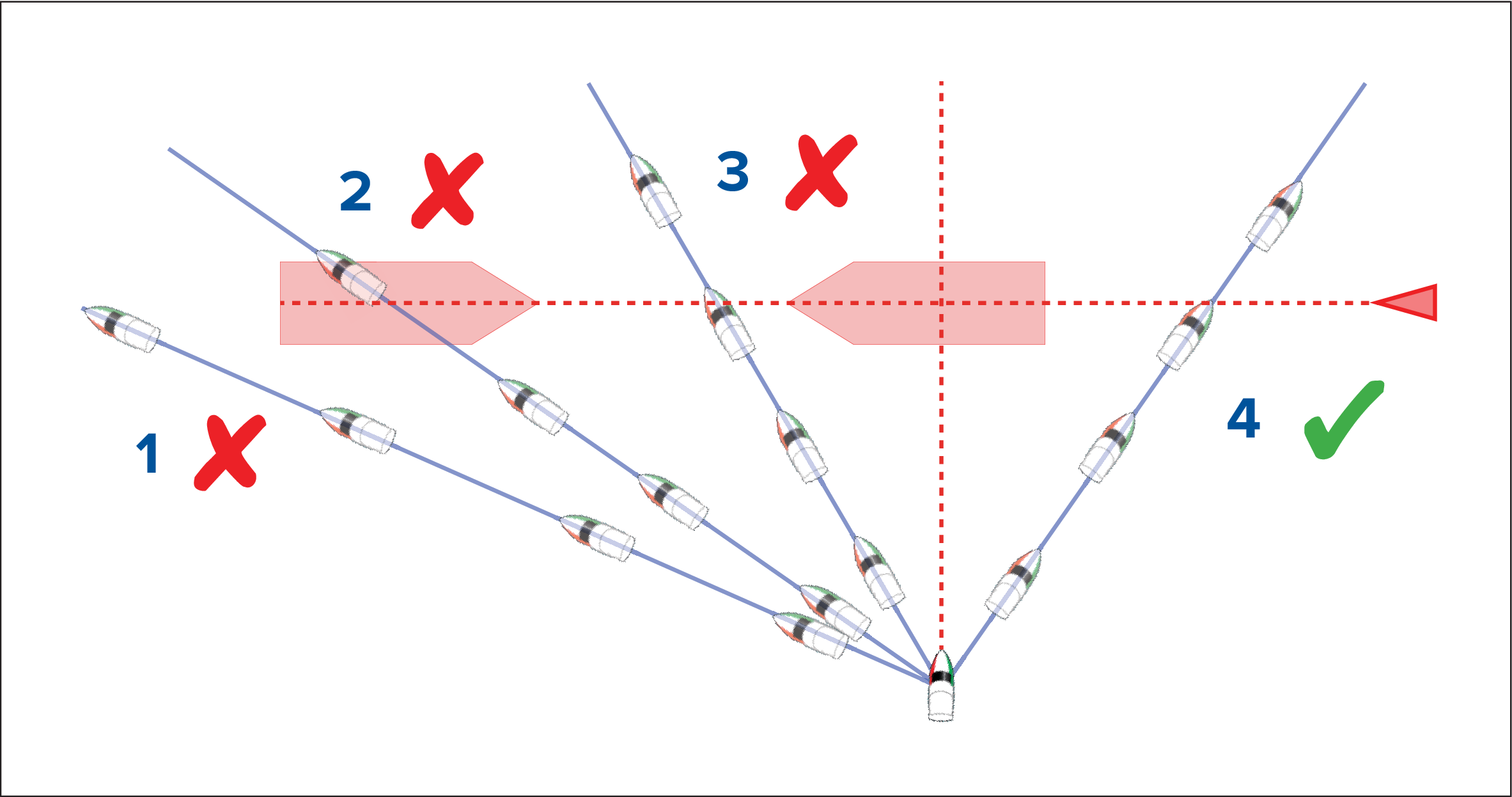
- Course alteration to pass ahead of the Interception zone [Not recommended] — As the target vessel is moving faster than your vessel you will pass astern of the target.
- Course alteration to pass ahead of the first Interception zone [Not recommended] — Although this course alteration is sufficient to avoid a potential bow-to-bow collision, it has created a second Interception zone where the target may now run you down from behind.
- Course alteration to pass between the 2 Interception zones [Not recommended] — Although this may seem like the quickest option, proceed with caution, as the gap between the 2 Interception zones can close quickly, especially when your vessel slows down.
- Course alteration to clear astern of the target vessel and its Interception zone. This would be the preferred manoeuvre as it correctly alters your vessel’s course so that it is clear of the target’s Interception zone, and passes safely astern of the target. This manoeuvre also clearly indicates to the target vessel your change of course.
Figure 2. Scenario 2 Speed change examples
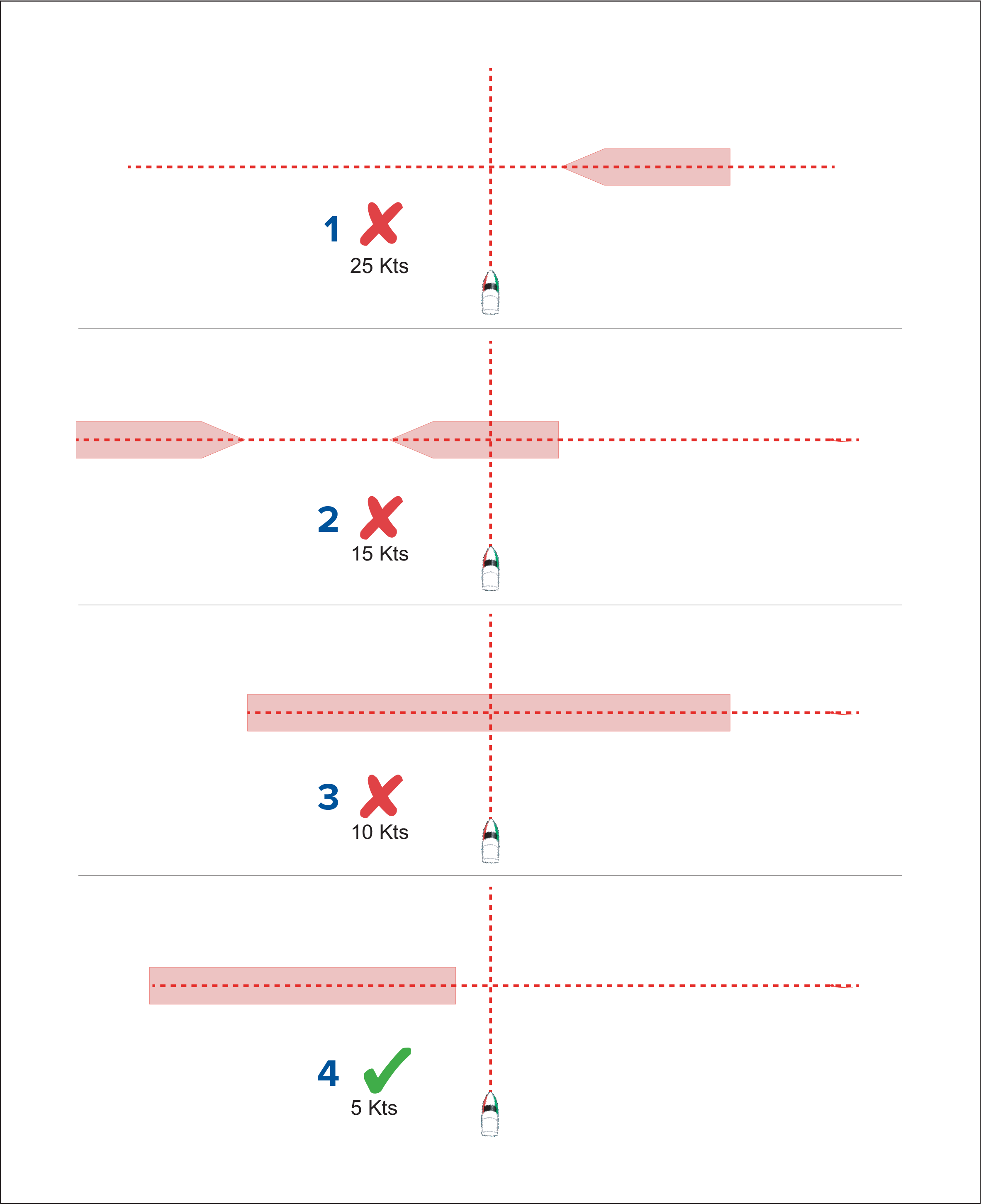
- Speeding up [Not recommended] — Increasing vessel speed to pass ahead of the target vessel. Proceed with caution, there is always an inherent risk when passing in front of other vessels.
- No change [Not recommended] — Not changing speed or course may result in a collision.
- Slowing down [Not recommended] — Slowing down slightly may result in the 2 Interception zones closing up or merging into a single zone.
- Slowing down — Slowing down a sufficient amount will allow the target vessel to pass safely ahead of your vessel, avoiding the Interception zone(s).
Example scenario 3 — Both vessels travelling at the same speed
| Note: These scenarios are examples provided for guidance only. |
When both vessels are travelling at the same speed, course alterations should be made in accordance with the guidance provided in examples 1 and 2.
Speed changeWhen both vessels are travelling at the same speed, altering your speed will change the collision scenario to one of the scenarios detailed in examples 1 and 2.
Target intercept
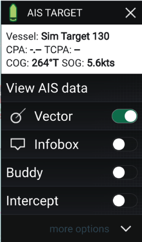
Pre-requisites:
- It is vital to have a good understanding of the International Regulations for Preventing Collisions at Sea (IRPCS / COLREGS), to ensure all actions taken are in accordance with the IRPCS. For more information on IRPCS / COLREGS, refer to: IRPCS
- You must be familiar with the AIS feature.
- You must have a thorough understanding of the Target interception feature and its implications before attempting to use it in a real life scenario.
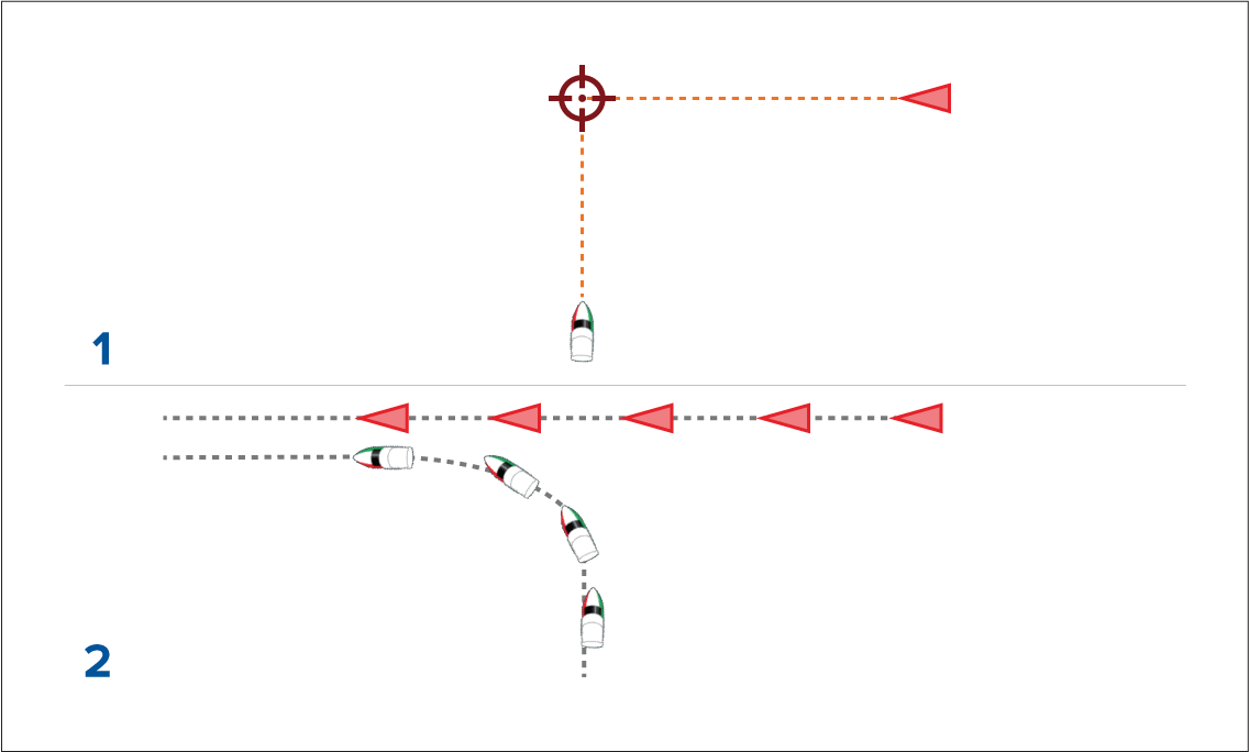
- Initial Target interception graphics.
- Actual vessel movements to perform the rendezvous.
Tides mode
Note:
|
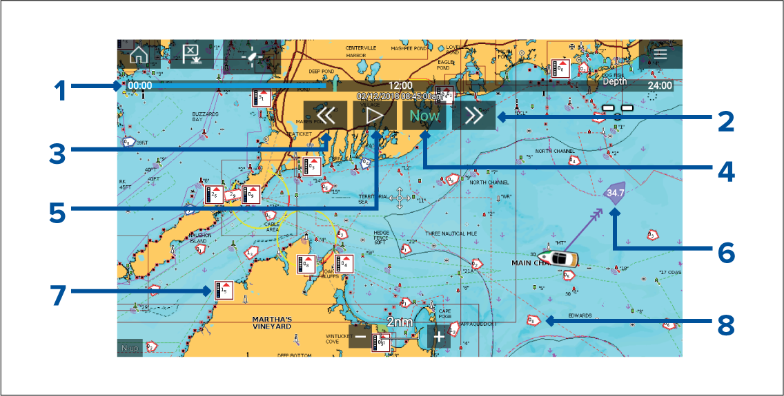
- Animation progress bar — The progress bar is Blue for the current 24 hour period, or Green when playing animations from a different day.
- Skip forwards — Skips forwards in user defined intervals, when the end of the progress bar is reached skipping forward will progress to the next day.
- Skip backwards — Skips backwards in user defined intervals. When the beginning of the progress bar is reached, skipping backward will regress to the previous day.
- Skip to the actual date / time — Position data is required from your GNSS (GPS) receiver to obtain current date and time.
- Play / Pause animation — When the animation is playing it will cycle through the current 24 hour period continuously.
- Own vessel tide (Set and Drift) vector.
- Dynamic tide height graphic.
- Dynamic current graphic.
|
Important:
The data provided in the Tide and Current graphs and graphics is for information purposes only and must NOT be relied upon as a substitute for prudent navigation. Only official government charts and notices to mariners contain all the information needed for safe navigation. |
Using animation controls
You can define the User skip time interval form the Advanced menu: .
Setting a specific date for animations
Tide station information
Tide station symbol

|
The location of Tide stations is marked on the Chart using a diamond-shaped symbol with a ‘T’ in the middle.
|
Dynamic tide graphic
Using Navionics cartography, when the Tides layer is enabled or when the Chart app is in Tides mode, the standard symbol is replaced with a dynamic Tide height graphic:
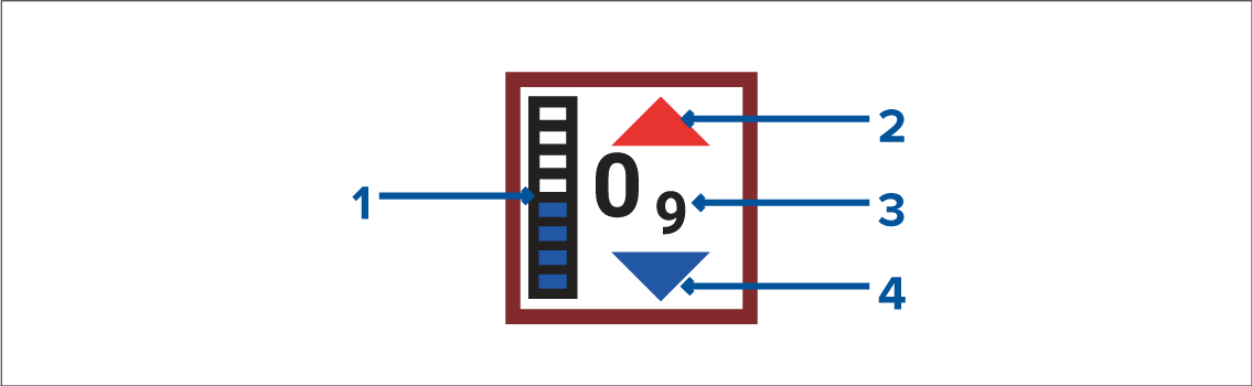
- Tide bar — The tide bar plots the current tide height against the maximum predicted tide height for that day.
- Red arrow indicates tide height is increasing.
- Tide height — Tide height is displayed in user-selected depth units, with decimals displayed in subscript. Decimals are not shown for values of 10 or greater.
- Blue arrow indicates tide height is decreasing.
Tide graph
Tide graphs are available with applicable Navionics and C-Map cartography by selecting more options and then Tide station from the Tide station’s context menu.
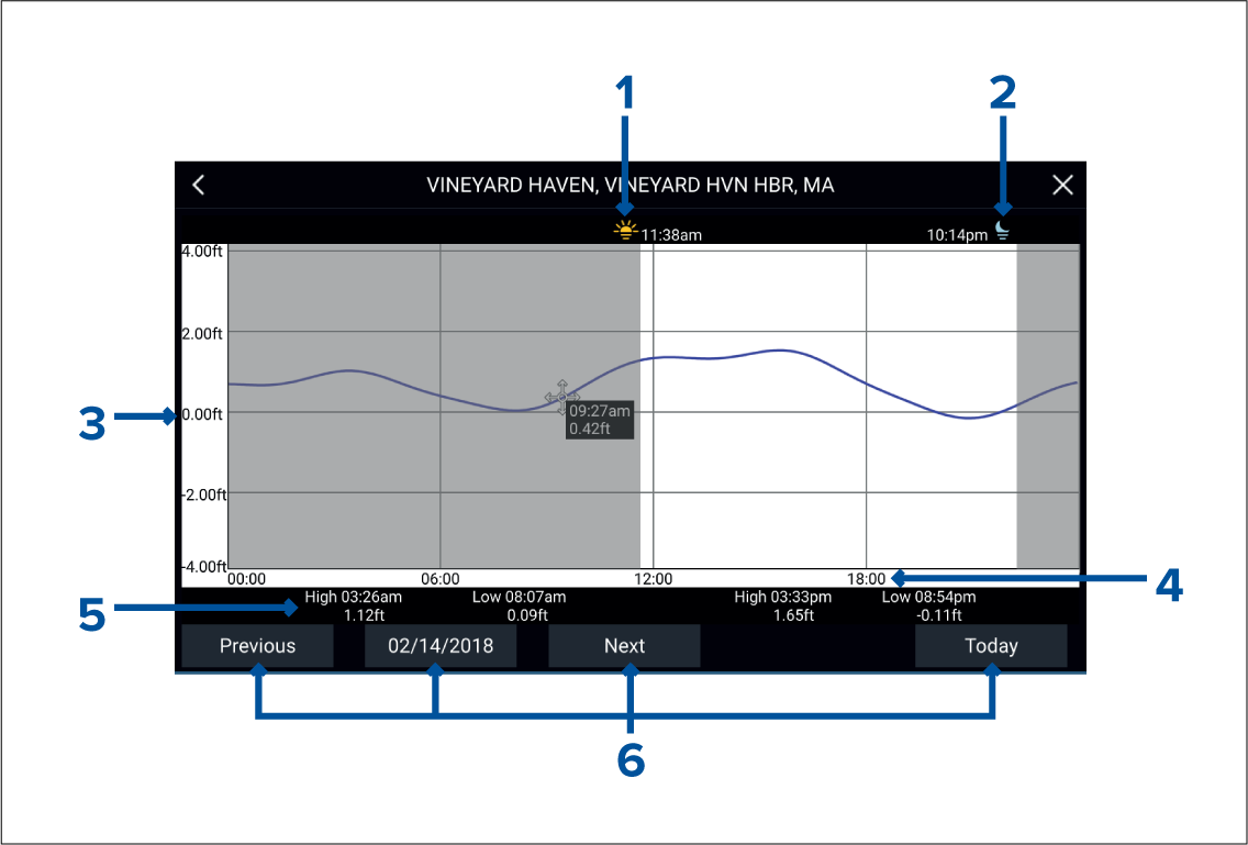
- Sunrise — Indicates time of sunrise.
- Sunset — Indicates time of sunset.
- Height — Provides tide height in selected units.
- Time — Indicates time of day.
- Low / High tide — Indicates the time of low and high tides.
- Time and date options — Use the buttons to view previous, next or today’s tide predictions, or enter a date by selecting the date field.
Current station information
Current station symbol

|
The location of Current stations is marked on the Chart using a diamond-shaped symbol with a ‘C’ in the middle.
|
Dynamic current graphic
When the Tides layer is enabled or when the Chart app is in Tides mode, the standard symbol is replaced with a dynamic Current graphic.
|
When using Navionics cartography the dynamic Current graphic is an arrow pointing in the direction of the current flow. Arrow length indicates the speed of the current; the longer the arrow, the faster the speed. The arrow’s border indicates current status:
Current speed is shown inside the arrow. Current speed is displayed in user-selected speed units, with decimals displayed in subscript. Decimals are not shown for values of 10 or greater. If tidal conditions are “slack”, the word “SLACK” appears in a box with a Blue border. |
When using C-Map cartography, arrows are used to indicate the direction of current flow. The size and color of the arrow indicates the strength of the current:

|
Yellow |
0 to 0.1 Knots |

|
Yellow |
0.2 to 1.0 Knots |

|
Orange |
1.1 to 2.0 Knots |

|
Orange |
2.1 to 3.0 Knots |

|
Red |
>3.0 Knots |
Current graph
Current graphs are available by selecting more options and then Current station from the Current station’s context menu.
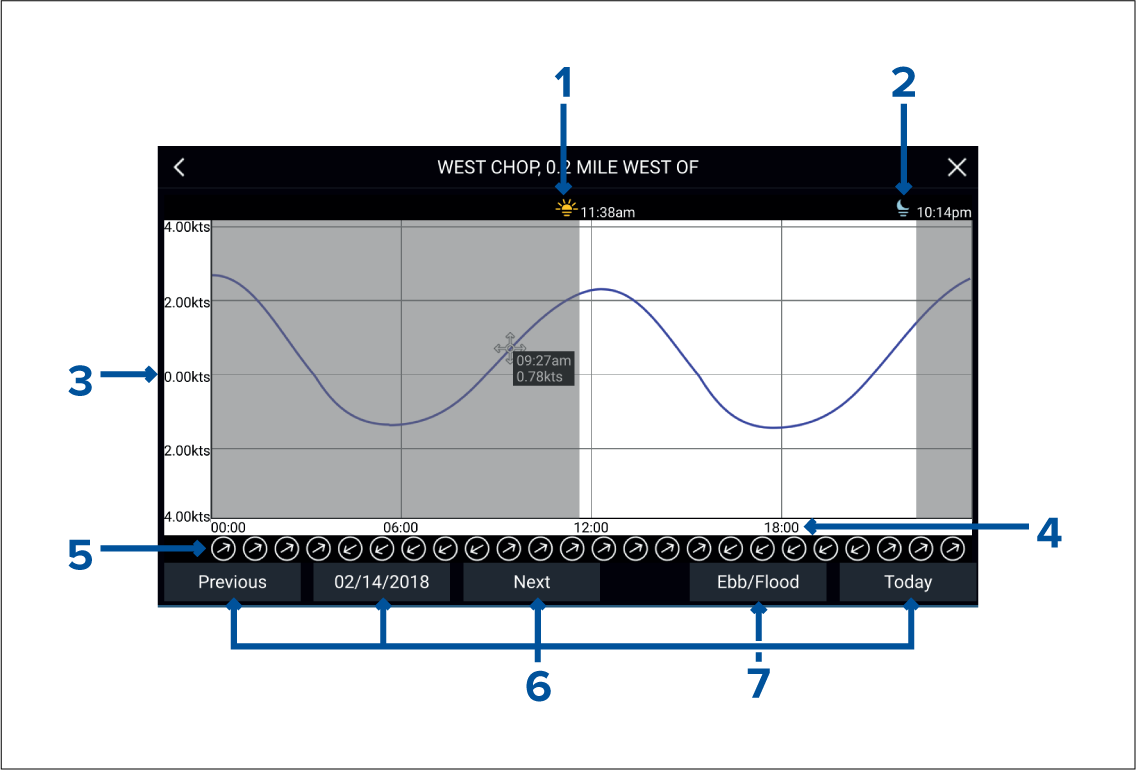
- Sunrise — Indicates time of sunrise.
- Sunset — Indicates time of sunset.
- Speed — Provides current speed in selected units.
- Time — Indicates time of day.
- Direction — Indicates the direction of the current (relative to North).
- Time and date options — Use the buttons to view previous, next or today’s tide predictions, or enter a date by selecting the date field.
- Ebb / Flood — Displays a list showing ebb, slack and flood tides.
Displaying tide or current graphs
RealBathy ™
When using the RealBathy ™ feature, new contour lines are drawn in realtime on the screen based on your transducer’s depth readings. Color shading is used to reflect depth, with the darkest shades signifying the shallowest area. The sonar data is recorded to the inserted memory card.
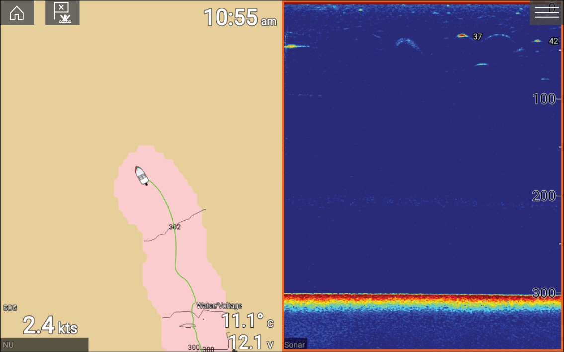
Requirements
The Realbathy feature requires the following:
- LightHouse ™ software version 3.9 or later.
- LightHouse ™ vector based charts, that include tide station information for the location you wish to survey.
- MicroSD card with sufficient free space to record depth and bathymetry data.
- You must ascertain the distance above the bottom face of your depth transducer to the waterline, as shown in the following illustration:
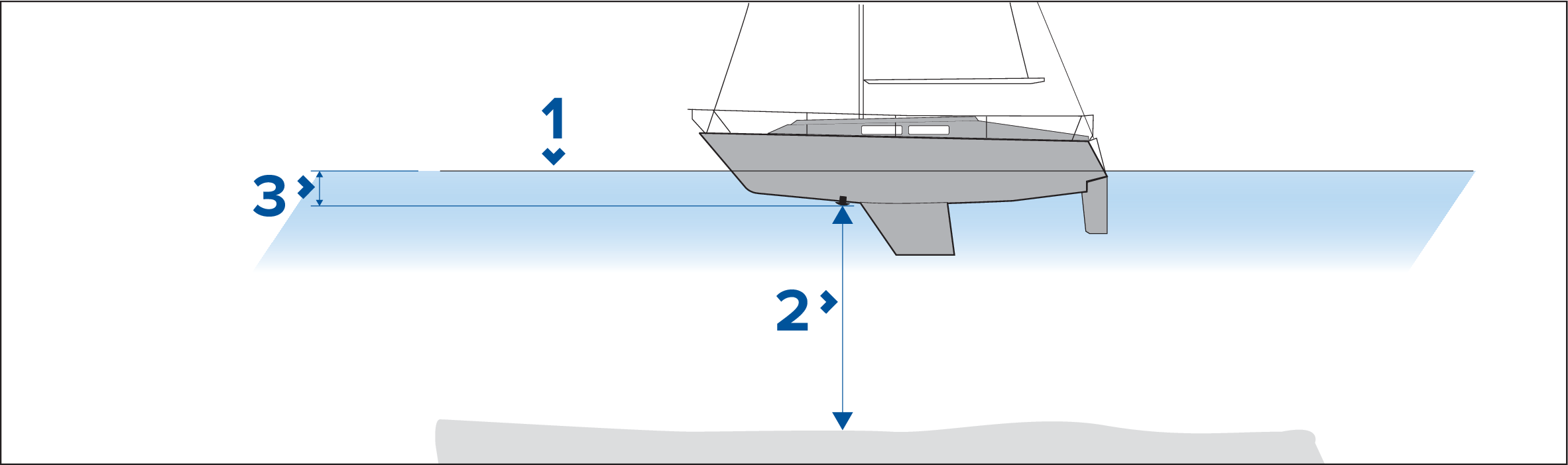
- Waterline.
- Water depth below transducer face.
- Distance above the bottom face of your depth transducer to the waterline.
Setting up and creating RealBathy contours
Important:
|
- None — No corrections are made.
- Tidal — Uses nearby tide station data to correct height. When Tidal is selected a tidal station search is performed and a list of available stations is displayed. Select the closest tide station to your location.
- Lake level — User specified value using the water level marker for your location.
|
Note:
To ensure accurate contour depths it is recommended that:
|
Find nearest
When an object is selected, the Nearby objects option is available from the object context menu.
Object selection find nearest
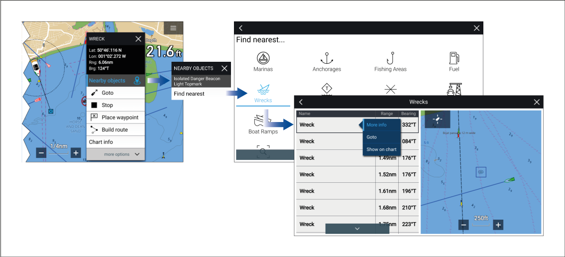
Selecting Nearby objects and then Find Nearest will display the Find nearest options page where you can select the type of place or object you want to search for.
Selecting an option will display a list of all nearby objects for that type. The list is sorted by an object’s proximity to the selected location. However, the Range and Bearing displayed is relative to your vessel’s position.
Location selection find nearest
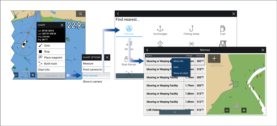
Pressing and holding on a location will open the Chart context menu, selecting more options and then Find nearest will display the Find nearest options page where you can select the type of place or object you want to search for.
Selecting an option will display a list of all nearby objects for that type. The list is sorted by an object’s proximity to the selected location. However, the Range and Bearing displayed is relative to your vessel’s position.
Find nearest options
The options available on the find nearest page depend on the cartography type you are using:
- Marinas (LightHouse Charts, Navionics, C-Map)
- Anchorages (LightHouse Charts)
- Fishing Areas (LightHouse Charts)
- Fuel (LightHouse Charts)
- Wrecks (LightHouse Charts, Navionics, C-Map)
- Tides/Currents (LightHouse Charts, Navionics, C-Map)
- Lakes (Navionics, C-Map)
- Obstructions (LightHouse Charts, Navionics, C-Map)
- Ports/Services (LightHouse Charts, Navionics, C-Map)
- Boat Ramps (LightHouse Charts)
- Food & Drink (LightHouse Charts)
- Toilets (LightHouse Charts)
- Beach/Swim/Recreation (LightHouse Charts)
- Search for port (LightHouse Charts, Navionics, C-Map)
- Businesses (Navionics)
- Point of interest (C-Map)
- Outdoor Recreational Areas (ORA) (C-Map)
- ORA Services (C-Map)
List options
From the list of found objects or places the following pop-over options are available for each item in the list:
- View more information about the object by selecting More info.
- Navigate to the selected object by selecting Goto.
- Create an automatic route to the selected object by selecting Autoroute to, if available.
- Display the selected object in the Chart app by selecting Show on chart.
When an item from the list is selected the LiveView on the right of the screen will highlight and zoom to the selected object.
Measure
The measure feature is available from the Chart context menu: .
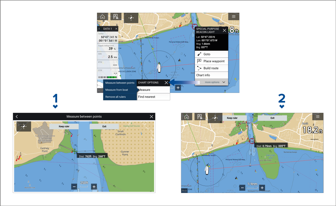
- Point to point ruler.
- Vessel to point ruler.
Multiple rulers can be created and displayed simultaneously.
Measuring vessel to point
A ruler line is drawn on the screen from your vessel’s location to the cursor’s location. The distance and bearing from your vessel is also displayed in an information box.
The ruler will be permanently displayed onscreen, the vessel end of the ruler will move with your vessel updating distance and bearing as you travel.
Measuring point to point
The ruler will be permanently displayed onscreen.
SonarChart ™ Live
| Note: Before using SonarChart ™ Live ensure you have correctly configured your transducer depth settings. |
When using SonarChart ™ Live, new contour lines are drawn in real time on the screen based on your transducer’s depth readings. Color shading is used to reflect depth, with dark red signifying the shallowest area. The sonar data is recorded to your cartography card and is shared with Navionics when you update your chart card online.
Enabling SonarChart Live
UAV Chart integration
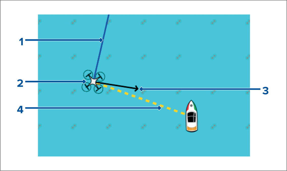
|
1 |
UAV COG The direction of the Blue line indicates the UAV’s current Course Over Ground (COG). The length of the line indicates the UAV’s predicted position when the specified vector Reference period has passed. The Vector Reference period can be adjusted from the vessel icon’s context menu. |
|
2 |
UAV Icon Displayed when the UAV option is enabled in the Chart app settings, and your UAV has a GNSS (GPS) position fix. |
|
3 |
Camera heading The Black Camera heading arrow is fixed to provide an indication of the direction the UAV’s camera is pointing towards. |
|
4 |
Line to vessel The Yellow dotted line represents the angle of the UAV’s position relative to your vessel. |
Showing or hiding the UAV icon
Performing a UAV Goto
You can stop a UAV Goto at anytime by selecting the Red Cancel UAV Goto that is displayed onscreen in the UAV app, when a UAV Goto is active. Cancelling a UAV Goto will stop the Goto action and the UAV will hover in its current location.
A UAV Goto can be cancelled at any time by selecting Stop UAV Goto from the Chart context menu.
ClearCruise ™ Augmented Reality
Augmented Reality features must also be enabled and configured in the Video app.
With the Augmented Reality features enabled, the AIS Target, Waypoint and Chart Object data available in the Chart app will also be available in the video app, where the data will be overlaid onto the live video feed.
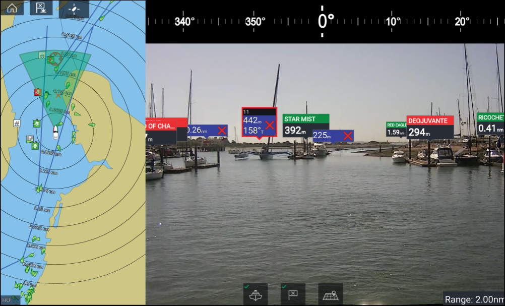
For further information on ClearCruise ™ Augmented Reality, refer to ClearCruise ™ features .
Field of View
Chart objects that are within the scope of the displayed FOV cone will be displayed in the Video app as “flags”. For more information on flags, refer to Augmented Reality flags
The area of coverage of the FOV cone is determined by:
- The camera’s horizontal Field of View (FOV). This setting can be adjusted in the Video app: .
- The Augmented Reality Range Limit. For more information refer to Range limit . You can also manually specify the maximum range limit; refer to ClearCruise settings (Augmented Reality) for more information. When you adjust this setting, the FOV cone in the Chart app will change accordingly.
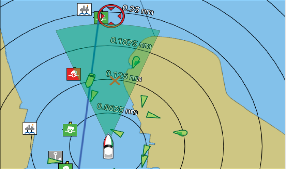
The FOV cone can be enabled/disabled in the Chart app settings: .
Chart settings menu
Cartography
|
Settings |
Description |
Options |
|
|---|---|---|---|
|
LightHouse Chart Navionics C-MAP |
Allows you to select the cartography that you want to use in the current Chart app. |
|
Layers tab
|
Settings |
Description |
Chart vendor and Layer options |
|
|---|---|---|---|
|
Layer options:
|
Allows you to select the level of detail displayed onscreen for vector-based cartography. |
Chart vendor:
|
|
|
Layer options:
|
Adjust the display size of chart objects. |
Chart vendor:
|
|
|
Layer options:
|
Switch between a brighter or darker chart background. |
Chart vendor:
|
|
|
Layer options:
|
Switch between Leisure and Government chart presentation styles. |
Chart vendor:
|
|
|
Layer options:
|
Enables and disables the display of AIS targets in the Chart app. Requires AIS hardware. |
Chart vendor:
|
|
|
Layer options:
|
Enables and disables the display of a photographic aerial overlay. |
Chart vendor:
|
|
|
Layer options:
|
Enables and disables the display of Radar-like range rings in the Chart app. |
Chart vendor:
|
|
|
Layer options:
|
Field of View Enables and disables the ClearCruise ™ Augmented Reality (AR) camera’s field of view (FOV) overlay in the Chart app. |
Chart vendor:
|
|
|
Layer options:
|
Enables and disables the display of your Radar scanner’s image in the Chart app. Requires Radar scanner hardware. |
Chart vendor:
|
|
|
Layer options:
|
Enables Weather Radar precipitation data overlay in the Chart app. Only available when connected to a compatible SiriusXM weather receiver with a valid subscription. |
Chart vendor:
Layer options:
|
|
|
Layer options:
|
Enables and disables the display of Tide and Current graphics at Tide and Current stations in the Chart app. |
Chart vendor:
|
|
|
Layer options:
|
Enables and disables the display of enhanced street details and points of interest. |
Chart vendor:
|
|
|
Layer options:
|
Displays the UAV icon, the UAV heading (camera direction), UAV COG and a line between the UAV and your vessel. |
Chart vendor:
|
|
|
Layer options:
|
Enables the collision avoidance interception zone layer for AIS targets. Only available when the AIS layer is enabled.
|
Chart vendor:
|
|
|
Layer options:
|
Enables the collision avoidance interception zone layer for Radar targets. Only available when the Radar layer is enabled.
|
Chart vendor:
|
|
|
Layer options:
|
Enables and disables the magnification of useful icons and text, making them easier to read. |
Chart vendor:
|
|
|
Layer options:
|
Enables and disables the display of crowd-sourced data. |
Chart vendor:
|
|
|
Layer options:
|
Enables and disables the display of High Resolution Bathymetry charts, which provide improved bottom detail, contours and structure. |
Chart vendor:
|
|
|
Layer options:
|
Allows you to display easy-to-use information pages about fishing locations including fish type, size, depth, and reef and bottom composition. |
Chart vendor:
|
|
|
Marine protected areas Layer options:
|
Allows clear identification of areas where commercial and recreational fishing is prohibited or restricted. |
Chart vendor:
|
|
|
Fishing AOI Layer options:
|
Enables and disables the display of Fishing AOIs (Areas Of Interest). |
Chart vendor:
|
|
|
Layer options:
|
Enables and disables the display of crowd-sourced data. |
Chart vendor:
|
Depths tab
|
Settings |
Description |
Chart vendor and Setting options |
|
|---|---|---|---|
|
Show soundings Setting options:
|
Enables and disables the display of depth soundings on the chart. When set to Manual, depth soundings will be shown from zero to the maximum depth you specify. |
Chart vendor:
|
|
|
Show contours Setting options:
|
Enables and disables the display of depth contours on the chart. When set to Manual, contours will be shown from zero to the maximum depth you specify. |
Chart vendor:
|
|
|
Shallow water Setting options: Numeric value |
Determines the depth at which the Shallow contour is displayed. The Shallow contour cannot be set to a value greater than the Safety or Deep contour value. |
Chart vendor:
|
|
|
Safe water from Setting options: Numeric value |
Determines the depth at which the Safety contour is displayed. The Safety contour cannot be set to a value that is less than the Shallow contour or greater than the Deep contour. |
Chart vendor:
|
|
|
Deep water from Setting options: Numeric value |
Allows you to specify the depth at which Deep water will be displayed. |
Chart vendor:
|
|
|
Depth gradient Setting options:
|
Allows you to specify the gradient shade between shallow and deep. |
Chart vendor:
|
|
|
Deep water color Setting options:
|
Allows you to specify the color that will be used to display Deep water. |
Chart vendor:
|
|
|
Setting options:
|
Allows logging of depth and position data to your Navionics chart card. |
Chart vendor:
|
|
|
Setting options:
|
Enables and disables the Navionics SonarChart Live feature, which enables the realtime creation and display of high resolution bathymetry charts. |
Chart vendor:
|
|
|
Visibility Setting options:
|
Determines the level of transparency used when displaying SonarChart data. |
Chart vendor:
|
|
|
Tide correction Setting options:
|
Enables Sonar logging depth measurements to be offset by tide height data from nearby tide stations. |
Chart vendor:
|
|
|
Shallow depth shading Setting options:
|
Enables and disables the identification of areas deemed to be shallow. When set to On, a red hatched area is displayed in areas shallower than the specified depth. |
Chart vendor:
|
|
|
Density Setting options:
|
Determines the density of available depth contours. |
Chart vendor:
|
|
|
Setting options:
|
You can set up a Fishing Range by enabling Fishing Range and specifying a minimum and maximum depth. Areas on the chart that are between these depths will be colored White; areas outside of these depths will be colored Blue. |
Chart vendor:
|
|
|
Setting options:
|
Enables depth and position data to be recorded to memory card. |
Chart vendor:
|
|
|
Waterline to tdcr Setting options: Numeric value |
Enter the distance between the waterline and your depth transducer. |
Chart vendor:
|
|
|
Save to Setting options: Numeric value |
When a suitable MicroSD card has been inserted the free space available for recording depth data and RealBathy is displayed. . |
Chart vendor:
|
|
|
Setting options:
|
Displays previously recorded RealBathy ™ data saved on memory card on the chart. |
Chart vendor:
|
|
|
Visibility Setting options: Numeric value |
Determines the transparency of the RealBathy data and SonarChart live data displayed onscreen. |
Chart vendor:
|
|
|
Height correction Setting options:
|
Determines the level of height correction applied to RealBathy and depth data. |
Chart vendor:
|
|
|
Safety depth shading Setting options: Numeric value |
Determines the depth at which the Safety contour is displayed. |
Chart vendor:
|
|
|
Density Setting options:
|
Selects the density of available depth contours.
|
Chart vendor:
|
View & Motion tab
|
Settings |
Description |
Options |
|---|---|---|
|
Relative motion In Relative motion mode the vessel icon remains fixed onscreen and the chart area moves relative to your position. In this mode you can adjust your vessel’s fixed position using the Boat position setting. True motion In True motion mode the chart is fixed and your vessel icon moves around the chart. As your vessel’s position reaches the edge of the screen, the chart is redrawn to reveal the area in front of your vessel. Auto range In Auto range the largest possible scale is maintained that will display both your vessel and the destination / target waypoint simultaneously. |
|
|
|
North-up In North-up the top of the screen always points towards north. As your vessel’s heading changes, the vessel icon rotates accordingly. Head-up In Head-up the top of the screen always points towards your vessel’s current heading, and as your heading changes the chart rotates accordingly. Course-up In Course-up the top of the screen always points towards your destination, and as your destination changes the chart rotates accordingly. |
|
|
|
The boat position determines the position of your vessel icon onscreen. The default is Center but you can adjust this to provide a greater distance in front of your vessel. Your boat position can only be changed when Chart motion is set to Relative motion. |
|
|
|
All charts with Sync turned On will synchronize orientation and position. |
|
Laylines
|
Setting |
Description |
Options |
|---|---|---|
|
Sail Performance |
Choose between Layline types:
|
|
|
(Fixed angle) Upwind angle |
|
|
|
(Fixed angle) Downwind angle |
|
|
|
(Polar) Polar |
|
|
|
Display Layines on this chart |
|
|
|
Adjust for tides |
|
|
|
Boat type |
|
|
Advanced tab
|
Settings |
Description |
Options |
|---|---|---|
|
The orientation of the chart affects alignment relative to your vessel, route or North. |
|
|
|
Enhanced AIS targets |
Switches between using standard and enhanced AIS targets. |
|
|
Auto find ship |
When enabled the Chart app will automatically center to your vessel after 30 seconds. |
|
|
Enables use of Radar overlay without Heading data. |
|
|
|
Cursor info boxes |
Allows display of information pop-ups for targets and objects. |
|
|
Allows you to select the time interval used for the Tide and Current animations in Tides mode. |
|
|
|
Cartographic objects |
Enables and disables the display of cartographic objects. The settings available are dependent on the cartography in use. |
|
|
Chart appearance |
Allows you to change the appearance of the Chart app. The settings available are dependent on the cartography in use. |
|
|
My data appearance |
You can change how your User data appears in the Chart app. |
|
Weather settings tab
|
Settings |
Description |
|---|---|
|
Wind symbol |
Determines whether Arrows or Barbs are used for Wind direction graphics in Weather mode. |
|
Marine zone boundaries |
Determines whether marine boundaries are shown in Weather mode. |
|
Watchbox alerts |
Enables and disables Watchbox alerts. |
|
Watchbox range |
Determines the range from your vessel that Watchbox alerts are displayed |
|
Signal strength |
Displays the signal strength of a connected weather receiver. |
|
Receiver ESN |
Displays the Electronic Serial Number (ESN) of a connected weather receiver. |
|
Note:
The Weather settings tab is only displayed when the Chart app is set to Weather mode. |
Page settings tab
|
Settings |
Description |
|---|---|
|
Data Overlays |
Enables configuration of Data overlays, which overlay key information from connected sensors onto the Chart, Radar, Sonar and Camera apps. |
|
Edit split ratio |
Enables you to customize the position of the partitions in splitscreen app pages. For example, 50/50, 70/30 etc. |
Weather mode
Weather mode
To enter Weather mode, open the Chart app menu and select WEATHER.
Weather mode allows you to track weather systems in relation to your vessel by overlaying live, historical and forecasted weather data directly on the chart. In Weather mode you can also view animated weather graphics and read weather reports. Weather mode sets the Chart detail setting to Low and hides other data which increases the visibility of Weather data.
Important:
|
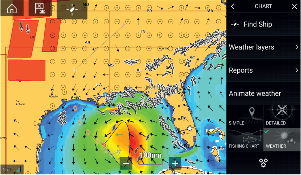
Weather symbols are organized into layers, accessible from the Chart menu: . Each layer can be enabled and disabled independently.
The following Layers are available:
| Weather radar | Surface pressure |
| Cities | Surface observation stations |
| Cloud top | Wind |
| Lightning | Watchbox |
| Sea surface temperature | Wave height |
| Storm cast | Wave period |
| Storm tracks | Wave direction |
In Weather mode the Chart orientation is fixed in North-Up.
Activating your SiriusXM receiver
|
Note:
Lighthouse Software Version
|
The following information is required to activate your SiriusXM receiver:
- Electronic Serial Number (ESN) — The ESN is printed on the product label located on the underside of your SiriusXM receiver. You can also access the ESN from the Weather settings tab in the Chart app: ().
- Current billing information (if you already have a valid subscription).
- Desired subscription package.
SR200 diagnostics mode
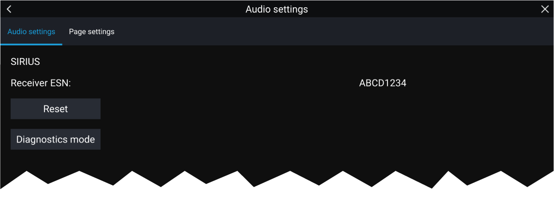
- Reset — Performs a factory reset and power cycle of the SR200.
- Diagnostics mode — Displays the SR200’s diagnostic information.
Weather receiver status
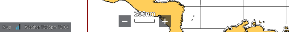
- chart orientation mode — (N-up) orientation is fixed in weather mode.
-
signal strength of your Weather receiver:
- Animated dots = no signal; searching for signal.
- 1 bar (orange) = poor signal strength.
- 3 bars (blue) = good signal strength.
- time and date related to the weather data being displayed.
Animated weather
Weather animations can be accessed in Weather mode by selecting Animate weather from the menu.
When Animate weather is selected the animation player controls and symbols representing the type of animated data available are displayed onscreen.
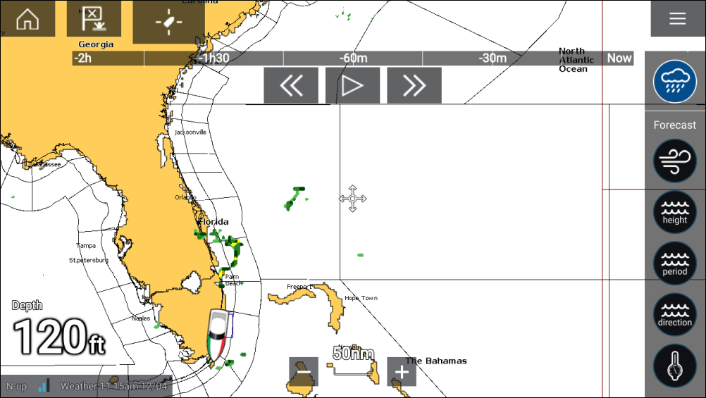
Player controls
Player controls include a progress bar, Play/Pause, Fast forward and rewind options.
Animated weather data
Duration of forecasts are dependent on subscription type.
|
Historical precipitation data for the previous 2 hours can be played. |

|
Offshore wind forecast for up to 48 hours. High resolution coastal and inland wind forecast for up to 24 hours. |
|
Offshore wave height forecast for up to 48 hours. High resolution coastal wave height forecast for up to 24 hours. Great Lakes wave height forecast for up to 24 hours. |
|
Offshore wave period forecast for up to 48 hours. Great Lakes wave period forecast for up to 24 hours. |
|
Offshore wave direction forecast for up to 48 hours. Great Lakes wave direction forecast for up to 24 hours. |
|
Surface pressure forecast for up to 48 hours. |
To exit Animate weather open the main Menu.
Weather mode context menu
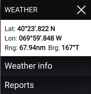
|
The context menu provides access to:
Depending on the symbol selected, the context menu also provides additional data when the Cities, Storm cast, Storm tracks or Watchbox option is selected. |
Weather Radar layer
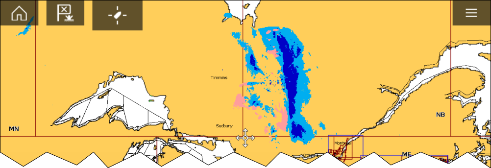
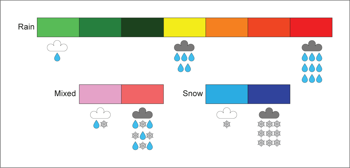
Cities and Surface observation stations layers
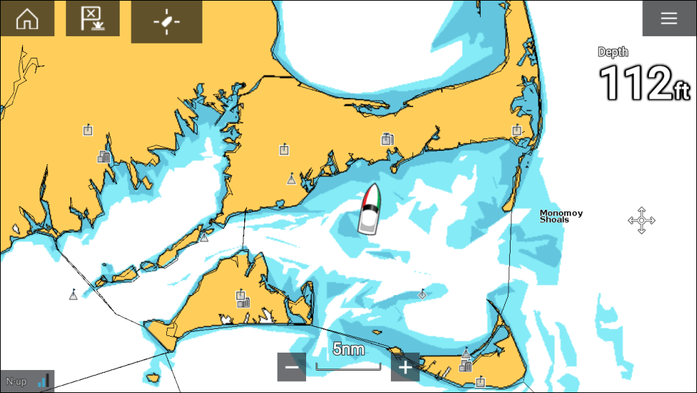
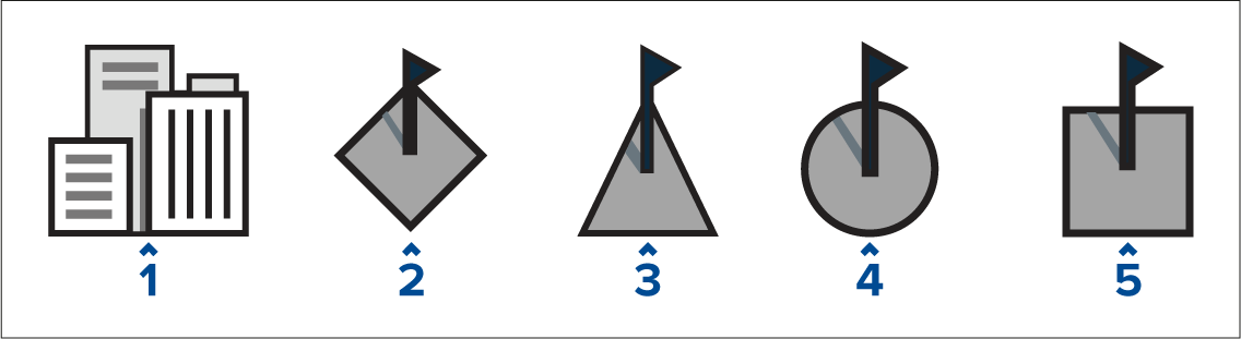
Cloud top and Lightning layers
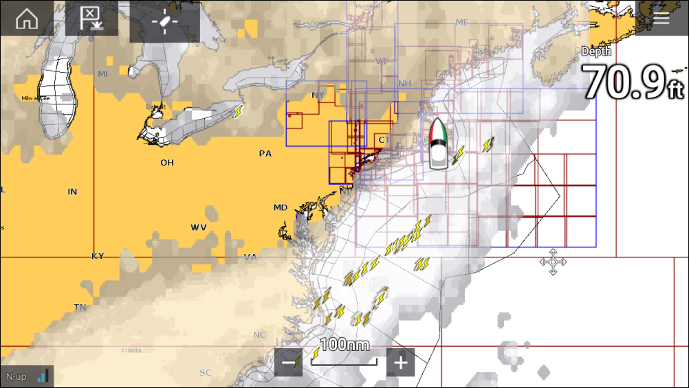
Cloud tops
Cloud tops use Gray shading to identify cloud top height. The shading changes at 5,000 feet increments, from Dark Gray to White. Clouds lower than 5,000 feet are not displayed.
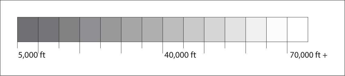
Lightning
The shade of the lightning symbols represent the time the lightning strike was detected.

|

|

|
|
0 to 5 minutes ago |
5 to 10 minutes ago |
10 to 15 minutes ago |
Storm cast and Storm tracks layers
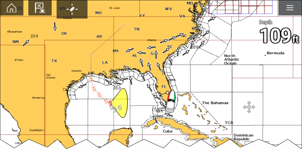
Storm tracks
Storm track symbols identify the type and time period of the storm.
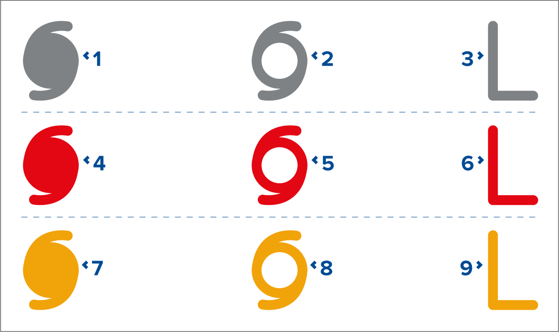
| Item | Category | Color | Description |
|---|---|---|---|
| 1, 2, 3 | Historical | Grey | Hurricane (Category 1–5) |
| 4, 5, 6 | Current | Red | Tropical storm |
| 7, 8, 9 | Forecast | Orange | Tropical disturbance, tropical depression |
Storm data is available from the context menu when a symbol is selected.
Surface wind fields (Wind Radii) are shown using colored shapes representing the wind field area and speed.
- Pink — wind speed = 64 knots or greater.
- Orange — wind speed = 50 knots or greater.
- Yellow — wind speed = 34 knots or greater.
Sea surface temperature and Surface pressure layers
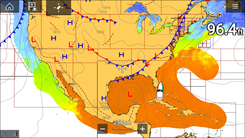
Sea surface temperature color coding
The colors used for the Sea surface temperature are shown below:
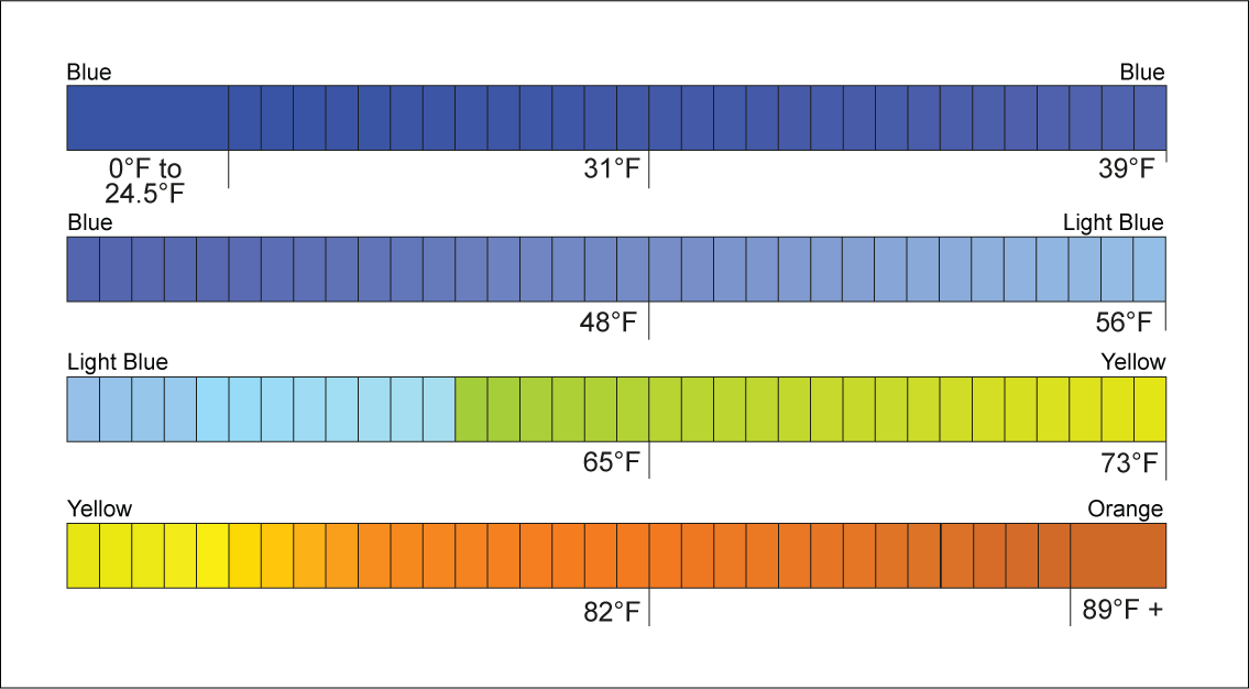
Surface pressure patterns
| Symbol | Description |
|---|---|

|
High / low pressure (Blue and Red) |

|
Warm front (Red) |

|
Cold front (Blue) |

|
Occluded front (Purple) |

|
Stationary front (Red-Blue) |

|
Trough (Brown) |

|
Squall line (Red) |

|
Dry line (Red) |

|
Isobars (Gray) |
Wind and Watchbox layers
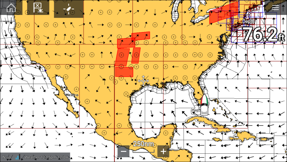
Wind arrows
The direction of the arrow indicates wind direction and the size of the arrow indicates wind speed, the larger the arrow the greater the wind speed. Where conditions are calm a circular symbol is used.
You can switch between using Arrows or Barbs for Wind data from the Weather tab of the Chart menu: .
Wind barbs
Wind barbs identify wind direction and speed.
Barbs provide a more accurate speed resolution than arrows.

Adding the half barbs, full barbs and flags together provides wind speed. The direction the barbs point towards indicates where the wind is coming from.
- Half barbs = 5 knots
- Full barbs = 10 knots
- Flag = 50 knots
Watchbox
Selecting Watchbox data from the Weather context menu display the data associated with the Watchbox alert.
Watchbox alerts can be enabled and disabled from the Chart menu: .
You can also adjust the area that is monitored for Watchbox alerts using the Watchbox range control on the Weather tab.
Wave direction, height and period layers
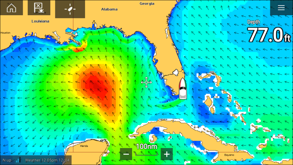
Wave direction
The Wave direction layer uses arrows to identify the direction of waves.
Wave height
Wave height uses colors to identify the height of waves. The colors used are as follows:
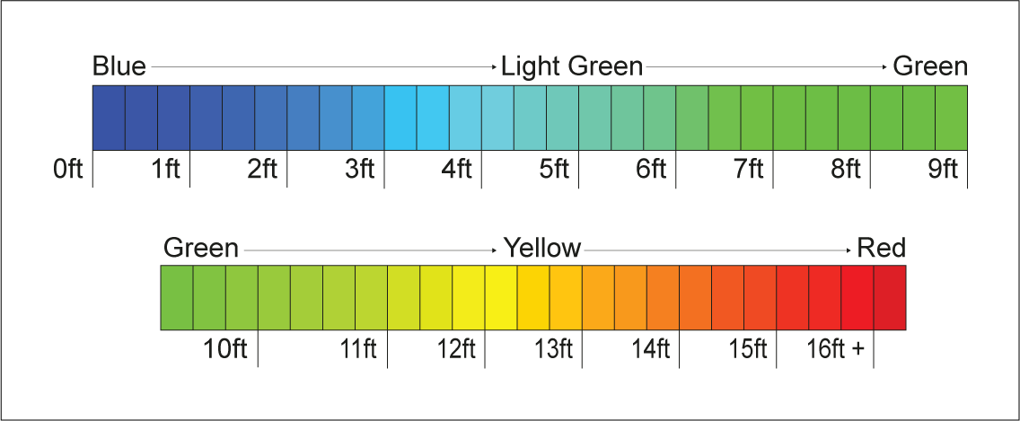
Wave period
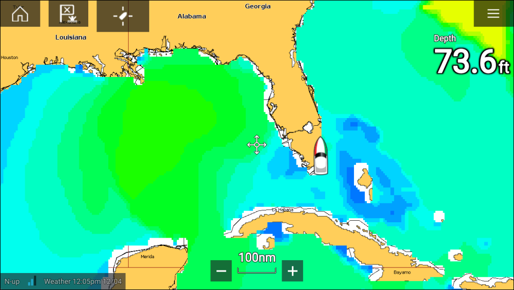
Wave period uses colors to identify the gap between successive waves. The colors used are as follows:
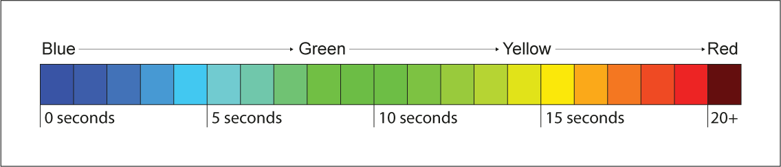
Fishfinder app
Fishfinder app overview
Multiple Sonar modules can be connected at the same time. Sonar modules can be internal (built-in to your MFD) or external (a separate box on your network).
For each instance of the Fishfinder app you can select which Sonar module and channel that you want to use, the Sonar module and channel selection will persist over a power cycle.
The Fishfinder app can be displayed in both Fullscreen and splitscreen app pages. App pages may consist of up to 4 instances of the Fishfinder app.
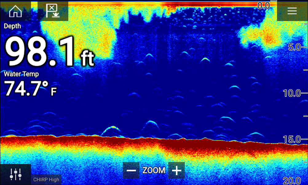
Fishfinder app controls
| Icon | Description | Action |
|---|---|---|
|
|
Home icon |
Takes you to the Homescreen |
|
|
Waypoint / MOB |
Place waypoint / activate Man overboard (MOB) alarm |
|
|
Pilot icon |
Opens and closes the Pilot Sidebar |
|
|
Menu icon |
Opens the app menu |

|
Image adjustment |
Displays onscreen sensitivity / image adjustment controls |
|
Pause |
Pause RealVision ™ 3D sonar image. |

|
Unpause |
When the Fishfinder app is paused, you can recommence scrolling by selecting the Unpause icon. |
|
|
Range/Zoom In |
When Auto range is enabled, pressing the plus icon activates Zoom mode, subsequent presses will increase the Zoom factor. When Range is set to Manual pressing the Plus icon decreases the distance displayed onscreen. Auto range can be enabled and disabled from the Menu: . |
|
|
Range/Zoom Out |
When in Zoom mode, pressing the minus icon will decrease the Zoom factor and finally revert to normal mode. When Range is set to Manual pressing the Minus icon increases the distance displayed onscreen. |
Touchscreen controls
- Pinch-to-zoom changes the magnification of the image.
- The Range control determines how far the sonar will ping.
- Press and hold onscreen to display the context menu
RealVision 3D controls
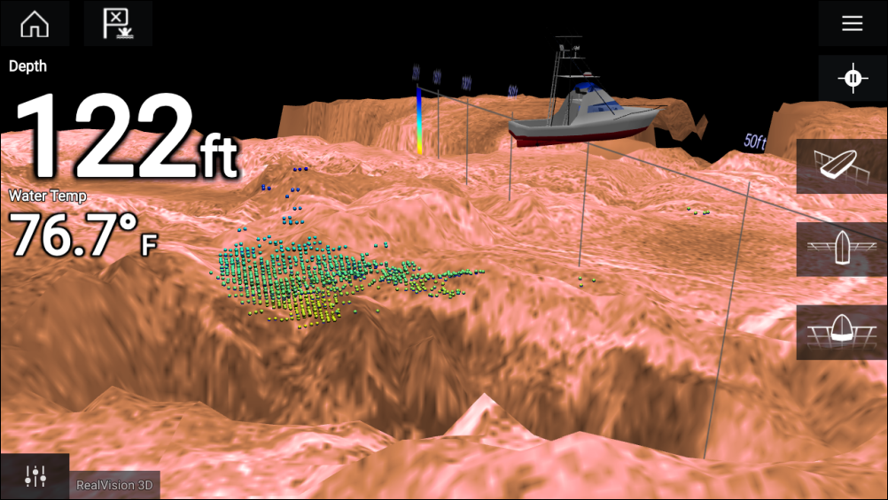
Touchscreen controls
- One finger swipe rotates the image.
- Two finger swipe pans the image around the screen.
- Pinch-to-zoom changes the magnification of the image.
- The Range control determines how far the sonar will ping.
- Press and hold onscreen to display the context menu
Physical buttons
- Ok button pauses Sonar scrolling.
- Back button resumes Sonar scrolling.
- Ok button when paused opens the context menu.
- Use the Uni-controller’s Directional (Up, Down, Left, Right) controls to rotate the image.
- Use the Uni-controller’s Rotary control or a RMK’s Range In and Range Out buttons to Range in and out.
Opening the Fishfinder app
Pre-requisites:
- Ensure your Sonar module is compatible (check the latest details available on the Raymarine website). If in doubt contact an authorized Raymarine dealer for advice.
- Ensure you have installed your Sonar module in accordance with the documentation that was supplied with the module.
The Fishfinder app will open in 1 of 4 states:
Please select a sonar channel
The first time you open a new app page that includes the Fishfinder app you will need to select a Sonar channel.

Select OK and then choose the Sonar channel you want to use from the list:
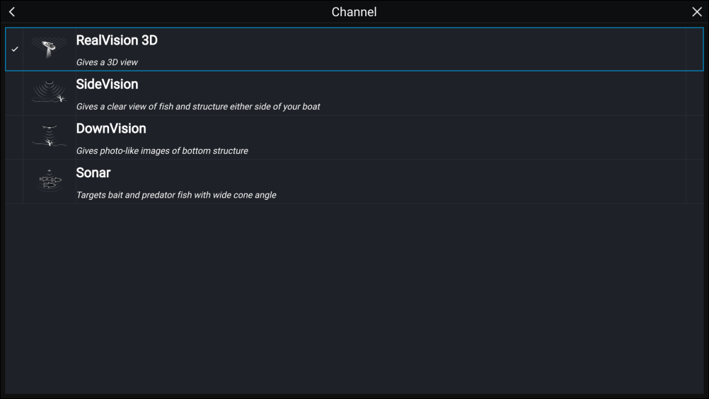
Sonar on and pinging
If your Fishfinder app has already been set up then when the Fishfinder app is opened the Sonar image will be displayed and start scrolling.
No sonar source available
If the ’No sonar source available’ warning is displayed then either:
- your sonar module is still powering up.
- your MFD cannot establish a connection with your external Sonar module
- your Internal Sonar module has no transducer connected.

Check your external sonar module’s network and power connection, check your MFD’s network or transducer connection ensuring the connections and cabling is correct and free from damage, then power cycle your system. If the Sonar module is still not found then refer to your equipment’s installation documentation for further troubleshooting information.
No transducer connected
If the ‘No transducer connected’ warning is displayed then your Sonar module cannot connect to your transducer.
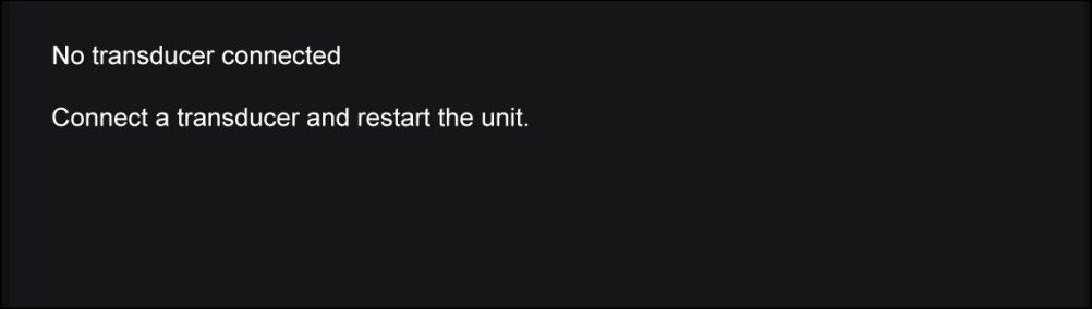
Check your transducer connection(s) are correct and free from damage, then power cycle your system. If the transducer is still not found then refer to your equipment’s installation documentation for further troubleshooting information.
Sonar channels
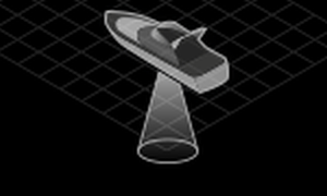
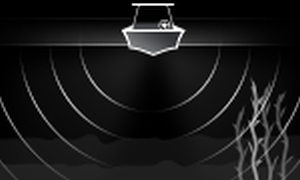
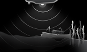
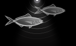
Selecting a Sonar channel
Placing a Waypoint (Sonar, DownVision and SideVision)
Placing a waypoint RealVision 3D
The Waypoint context menu and Red waypoint marker is displayed:
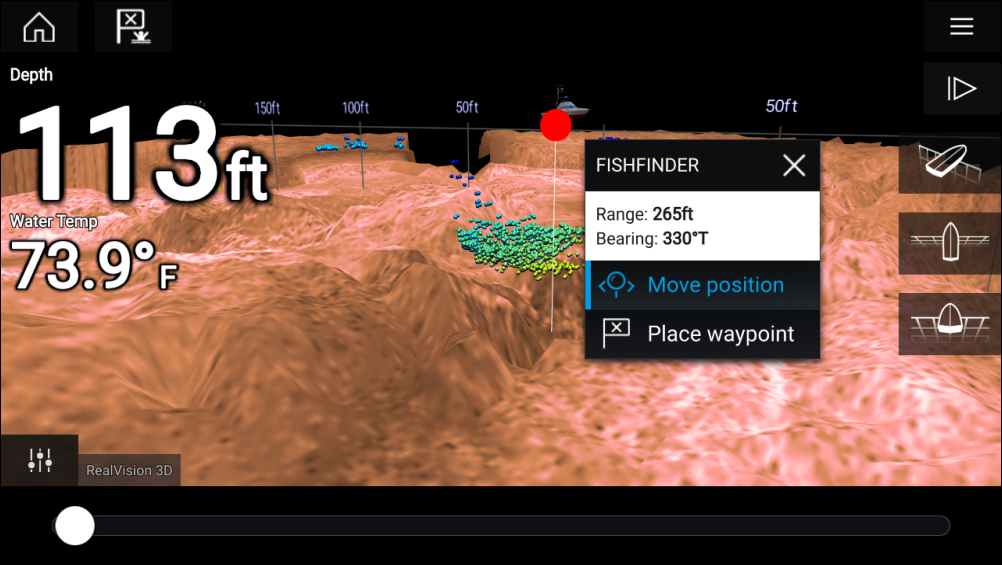
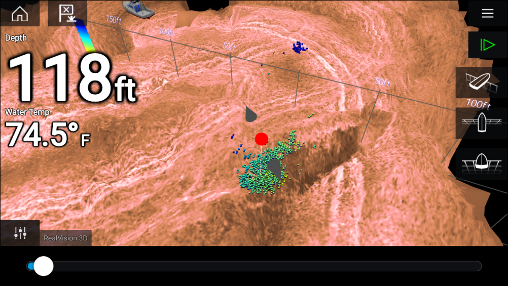
You can move the waypoint along its current axis by sliding 1 finger across the screen. You can also adjust the view onscreen using the usual 2 finger touch gestures.
Sonar scroll back
To activate sonar “scroll back”, perform the following:
- Sonar and DownVision — Swipe your finger left to right across the sonar screen.
- SideVision — Swipe your finger from the bottom to the top of the sonar screen.
- RealVision 3D — Select the onscreen Pause icon.
When sonar scroll back is active the sonar Scroll back bar and Unpause icons are displayed.
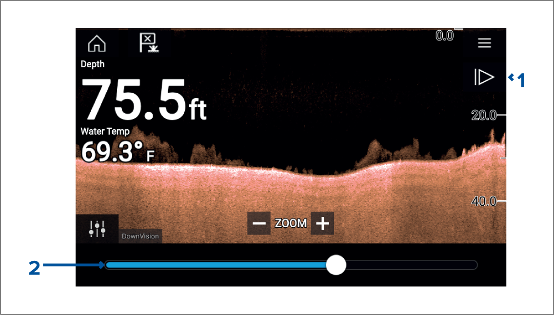
- Unpause — Selecting this option resumes live sonar scrolling.
- Scroll back bar — Use this to move back and forward through the available sonar history. You can either drag the position indicator right or left or select a specific location on the bar to jump to that position.
In Sonar, DownVision and SideVision channels, subsequent swipes will rewind the sonar history and swiping in the opposite direction will fast forward the sonar history.
Sonar sensitivity controls
The Sensitivity controls available are dependant upon the Sonar module in use.
| Control | Name | Description |
|---|---|---|

|
‘G’ Gain |
The control determines the signal strength at which target returns are shown onscreen. The Gain control can be set to Auto or Manual. Depending on Sonar module, in Auto you can add an offset of up to ± 50%. A higher value produces more target returns and noise onscreen. |

|
The control sets the lower limit for the color used for the strongest target returns. All target returns above this value are displayed in the strongest color. Those with a weaker value are divided equally between the remaining colors. The control can be set to Auto or Manual. Depending on Sonar module, in Auto you can add an offset of up to ± 50%. |
|

|
The control determines the amount of noise displayed onscreen by varying the gain throughout the water column. A lower value decreases the depth at which the control is applied. The control can be set to Auto or Manual. |
|

|
‘TVG’ Time Varied Gain |
The control determines the amount of attenuation applied throughout the water column to ensure that targets of a similar size appear the same regardless of depth. A higher value produces weaker targets and less noise onscreen. The control can be set to 1 of 3 Auto modes or can be set to Manual. |

|
All to Auto |
Sets all Sensitivity settings to Auto with 0% offset. |
Fishfinder settings menu
Sonar display tab
|
Settings |
Description |
Options |
|---|---|---|
|
Color palette |
Various color palettes are available to suit different conditions or your personal preference. |
List of color palettes. |
|
View selection buttons |
Enables and disables SideVision ™ Left, Right and Both onscreen channel selection icons. |
|
|
A-scope |
A-Scope mode provides a splitscreen view that includes the normal scrolling sonar image and a smaller pane which shows a ‘live’ image of what is directly below your transducer. |
|
|
Bottom lock |
Bottom lock flips the range indication so that the bottom always appears flat. |
|
|
Range lines |
Displays vertical range lines when viewing. |
|
|
Depth lines |
Displays horizontal depth lines. |
|
|
White line |
Displays a solid white line along the bottom contour. |
|
|
Bottom fill |
Displays a solid color fill for the bottom. |
|
|
Color threshold |
Color threshold determines the signal strength below which target returns are not shown. A low value results in only the strongest colors or lightest shades being displayed. |
|
|
Scroll speed |
Determines the scrolling speed for the Sonar image. |
|
RealVision ™ 3D — Sonar display tab
|
Settings |
Description |
Options |
|---|---|---|
|
Boat icon |
Choose which boat icon to use. |
List of available Boat icons. |
|
Image stabilization |
Uses RealVision ™ 3D transducer’s built-in sensors to counter-act the rocking motion of your vessel to produce a stable sonar image. |
|
|
Target colors |
Changes the color palette used for target returns. |
List of color palettes. |
|
Color targets by |
Changes the way targets are colored. Depth colors targets according to their depth, a gradient scale can be shown on the 3D grid to aid depth identification. Intensity colors targets according to their size, the bigger the target the darker the color used. |
|
|
Show targets as |
Changes the method of rendering targets, Point provides the highest resolution, Sphere provides a lower resolution but increases target size for increased visibility. |
|
|
Bottom colors |
Changes the color used for bottom structure. |
List of colors. |
|
Background |
Changes the color used for the app background. |
List of colors. |
|
View mode |
In GPS track mode the boat icon will remain in the same position and bottom structure and target detail will move in true relation to your vessel movements. In Scrolling image mode the sonar pings at a constant speed and displays a scrolling image behind the boat icon. |
|
Transducer tab
|
Settings |
Description |
Options |
|---|---|---|
|
Transducer |
Allows selection of Sonar transducer. |
List of available transducers. |
|
Display depth as |
Determines the position from where depth readings are taken from. |
|
|
Speed transducer |
Allows selection of Speed transducer. |
List of available transducers. |
|
Calibrate speed |
Allows you to enter an offset between actual measured speed and the current speed displayed by your transducer. |
Offset value. |
|
Enable temperature sensor |
Enables and disables the selected transducer’s temperature sensor. |
|
|
Calibrate temp |
Allows you to enter an offset between actual measured water temperature and the current temperature displayed by your transducer. |
Offset value. |
Sounder tab
|
Settings |
Description |
Options |
|---|---|---|
|
Sounder name |
Allows you to rename your sonar module. |
Onscreen keyboard. |
|
Ping enable |
Enables and disables transducer ping. |
|
|
Ping rate limit |
Allows you to restrict the transducer’s maximum ping rate to suit current conditions. |
|
|
Power mode |
Adjusts the transducer’s signal strength. In Auto the sonar module will automatically determine the optimal power based on current depth, speed and bottom signal. In Manual you can adjust the power to the desired level. |
|
|
Ping rate |
Hyper ping should be used at speeds of up to 40 knots in shallower waters (6 metres or less). When the depth reaches 6 metres or above the ping rate will automatically reduce to normal until depth conditions are met. |
|
|
Dual channel ping mode |
On sonar modules that offer simultaneous dual channel operation, such as the CP570, The ping mode can be changed. Auto the Fishfinder app will select the best mode chosen based on range settings. Independent pings maximizes ping rate but may introduce interference. Simultaneous pings reduced ping rate and reduces chance of interference. |
|
|
Tune frequency |
Enables manual tuning of non-CHIRP frequency channels. |
|
|
AHRS stabilization |
The AHRS built in to the RealVision ™ 3D transducer is used to stabilize the sonar image onscreen based on your vessel’s detected movements. |
|
|
Reverse Port/Starboard |
When a RV100 transducer is hull/step mounted the transducer can be installed with the cable orientated towards either the bow or the stern of the vessel. On installations where the transducer cable is orientated towards the stern of the vessel then the Reverse Port/Starboard control must be enabled. |
|
|
Interference rejection |
Removes interference caused by other transducers on your vessel or from vessels equipped with transducers close by. |
|
|
2nd echo rejection |
The control helps to remove false target returns or false bottom that can be caused by signal reflection. |
|
|
Reset sounder |
Resets the sonar module to factory default settings. |
|
|
Reset trip |
In installations that include a speed transducer connected via the sonar module a trip log is automatically recorded. Selecting this option resets the sonar module’s trip log. |
|
|
Note:
The fish detection tab is only available when viewing a high CHIRP sonar channel. |
Fish detection tab
|
Menu item and description |
Options |
|
|---|---|---|
|
Enables and disables audible beep when a target is detected that is considered to be a fish. |
|
|
|
Enables and disables display of a fish icon over targets considered to be fish. |
|
|
|
Enables and disables display of depth labels next to targets considered to be fish. |
|
|
|
Determines how sensitive the fish detection algorithm is. The higher the value, the more target returns will be considered to be fish. |
Values from 0 to 100 (75 (default) ). |
|
|
Ignore fish shallower than: Targets returns found in water shallower than the specified depth will not be considered to be fish.
|
0 ft to 1000 ft (3.3 ft (default) ) or equivalent units. |
|
|
Ignore fish deeper than: Targets returns found in water deeper than the specified depth will not be considered to be fish.
|
0 ft to 1000 ft (984 ft (default) ) or equivalent units. |
Page settings tab
|
Settings |
Description |
|---|---|
|
Data Overlays |
Enables configuration of Data overlays, which overlay key information from connected sensors onto the Chart, Radar, Sonar and Camera apps. |
|
Edit split ratio |
Enables you to customize the position of the partitions in splitscreen app pages. For example, 50/50, 70/30 etc. |
Radar app
Radar app overview
Up to 2 Radar scanners can be connected at the same time. However, only 1 Radar in a system can be a Quantum ™ Radar.
For each instance of the Radar app you can select which Radar scanner you want to use, the Radar scanner selection will persist over a power cycle.
The Radar app can be displayed in both Fullscreen and splitscreen app pages. App pages may consist of up to 2 instances of the Radar app.
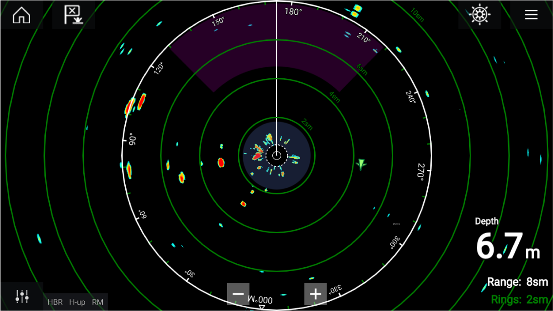
Tracked Radar targets and AIS targets are displayed using target symbols.
The Radar app allows you to configure alarms which are triggered when a target or object conflicts with the Dangerous targets or Guard Zone alarm settings.
The Range rings, bearing ring and VRM/EBLs can be used to identify a targets distance and heading in relation to your vessel.
Radar app controls
| Icon | Description | Action |
|---|---|---|
|
|
Home icon |
Takes you to the Homescreen |
|
|
Waypoint / MOB |
Place waypoint / activate Man Overboard (MOB) alarm |
|
|
Pilot icon |
Opens and closes the Pilot Sidebar |
|
|
Menu icon |
Opens the App menu |
|
|
Image adjustment |
Displays onscreen sensitivity / image adjustment controls |
|
Power Off |
Powers down the current Radar scanner |
|
Power On |
Powers up the selected Radar scanner |
|
Transmit |
Start Radar transmission |
|
|
Range In |
Decreases the distance displayed onscreen (minimum range: 1/16nm). |
|
|
Range Out |
Increases the distance displayed onscreen (up to your Radar scanner’s maximum range). |
Radar app context menu
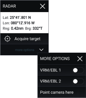
Camera tracking
2 options are available for camera tracking:
Camera tracking options are available from the Context menu in the Chart and Radar apps: , or .
Automatic tracking
You can use the Camera app settings to configure automatic tracking for AIS, Radar and MoB targets:
Radar feature comparison
Sensitivity controls
| Features/settings | Radar type |
|---|---|
|
Gain |
|
|
Color Gain |
|
|
Rain |
|
|
Sea Clutter |
|
|
FTC (Fast Time Constant) |
|
|
Power Boost |
|
|
Antenna Boost |
|
Gain Modes
| Features/settings | Radar type |
|---|---|
|
Buoy |
|
|
Harbor |
|
|
Coastal |
|
|
Offshore |
|
|
Bird |
|
|
Weather |
|
Features
| Features/settings | Radar type |
|---|---|
|
Doppler |
|
|
Dual Range |
|
|
Interference Rejection |
|
|
Interference Rejection Level |
|
|
Target Expansion |
|
|
Expansion Level |
|
|
Guard Zones |
|
|
Guard Zone Sensitivity |
|
|
Radar Targets |
|
|
Auto acquire (targets) |
|
|
Tuning |
|
|
Transmit Frequency |
|
|
Scanner Rotation Speed |
|
|
Sea Clutter Curve |
|
|
Parking Offset |
|
|
Antenna Size selection |
|
|
Timed Transmit |
|
|
Bearing Alignment |
|
|
MBS (Main Bang Suppression) Off |
|
|
Tuning Preset |
|
|
STC (Sensitivity Time Control) Preset |
|
|
VRM/EBL (Variable Range Markers/Electronic Bearing Line) |
|
|
Display Timing |
|
|
Max Range |
|
|
Colors |
|
Opening the Radar app
Pre-requisites:
- Ensure your Radar scanner is compatible, check the latest details available on the Raymarine website, if in doubt please contact an authorized Raymarine dealer for advice.
- Ensure you have installed your Radar scanner in accordance with the documentation that was supplied with your Radar.
The Radar app will open in 1 of 3 states:
Off/Not Connected

If the ‘Off/Not Connected’ message is displayed then:
- your Radar scanner may be powered down, or
- your MFD cannot establish a connection with your Radar scanner
Select On to power up your Radar. If the ‘Radar not found’ message is displayed then a connection could not be established, ensure that network and power connections to your Radar and MFD are correct and free from damage and then power cycle your system. If the Radar scanner can still not be found refer to your Radar’s installation documentation for further troubleshooting information.
Off

If the ‘Off’ message is displayed then your Wi-Fi connected Radar scanner is paired but powered off, select On to power up your Radar
Standby (Not transmitting)

If the ‘Standby’ message is displayed then select Transmit to begin transmitting.
Transmitting
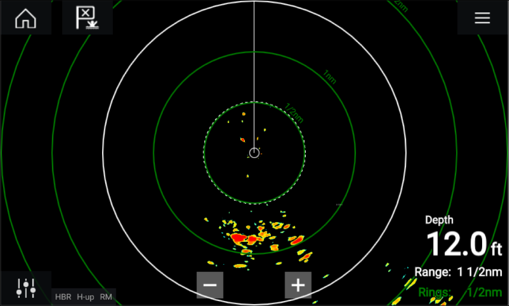
If your Radar scanner is connected, powered up and transmitting then the Radar image is displayed and echoes/targets are displayed onscreen.
Putting the radar into standby
Set up
Selecting a Radar scanner
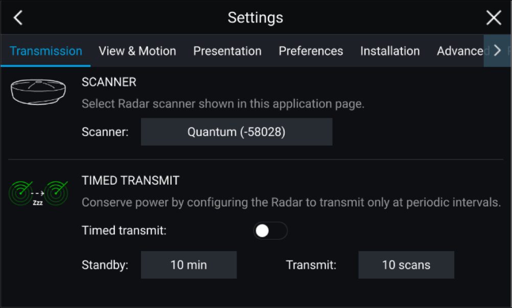

Dual range
To view both ranges you will need to configure a splitscreen, dual Radar, app page that displays the same Radar scanner in each window. You can then enable Dual Range mode and set the Channel for each window from the Transmission tab: .
Dual range limitations:
- Dual range cannot be enabled when Radar targets are being tracked (clear the target list and try again).
- When Dual range is enabled Radar target tracking is disabled.
- When Dual range is enabled Automatic Radar target acquisition is disabled.
- In Dual range the maximum rotation speed is 24rpm.
- When using a SuperHD Radar Antenna boost and Power boost controls are only applied to the Long range channel. Open Array Radar scanners running version 1.xx or 2.xx software will have the Short range channel’s maximum range restricted to 3 nm.
- When Dual range is enabled on a Radar scanner running version 1.xx or 2.xx software the Expansion control will be disabled.
Timed Radar transmission
The Radar will transmit for the specified number of rotations and then will switch to Standby for the specified time interval, the sequence will repeat until Timed Transmit is switched off.
The Timed transmit will revert to Off after a power cycle.
Setting open array antenna size
Bearing alignment
Checking alignment
Align the bow with a stationary object between 0.25 and 2 NM away.
Reduce the gain to make the target as small as possible on the screen.
Note the position of the object on the Radar screen. If the target is not under the ship’s heading marker (SHM), then bearing alignment adjustment is required.
Adjusting alignment
Adjust the Bearing alignment setting until the target object appears under the SHM.
Bearing alignment setting can be accessed from the Installation tab: .
| Note: Heading (HDG) is displayed in the Radar application. Please be aware that bearing alignment refers to the relative bearing of targets to the vessel's bow using visual checks / traditional means. |
Radar modes


Range and bearing
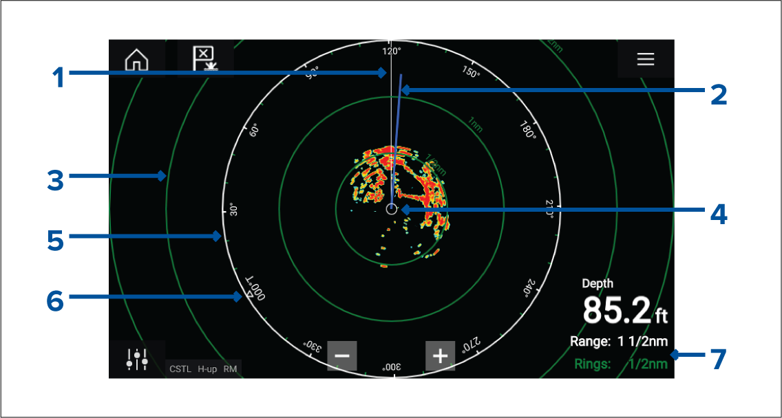
- SHM (Ships heading marker).
- COG/SOG line (Points in the direction of travel (COG), with the length of the vector providing an indication of speed (SOG)).
- Range rings.
- Vessel position.
- Range and bearing indicator (The White ring identifies the distance from your vessel to the top edge of the screen. Bearing indicators are also provided around the ring).
- North indicator (Always points North).
- Current displayed Range and Ring separation distance (Range: identifies the distance from your vessel to the top edge of the screen. Rings: identifies the distance between each Range Ring).
The displayed range can be adjusted at anytime using the Range controls.
Range rings can be switched off from the Presentation tab:
You can also choose whether to display a numerical range indicator against each ring using the Range ring labels: option.
VRM (Variable Range Marker) / EBL (Electronic Bearing Line)
or
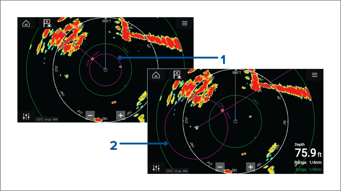
- Centered VRM/EBL You can use a ‘Centered’ (on your vessel) VRM/EBL to determine the range and bearing of targets in relation to your vessel.
- Floating VRM/EBL You can use a ‘Floating’ VRM/EBL to determine the range and bearing between 2 targets.
Editing a VRM-EBL
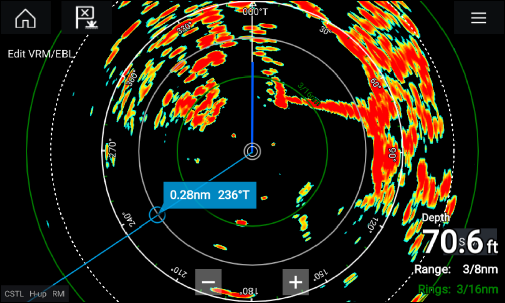
AIS targets
Tracked AIS targets are identified onscreen using target symbols.
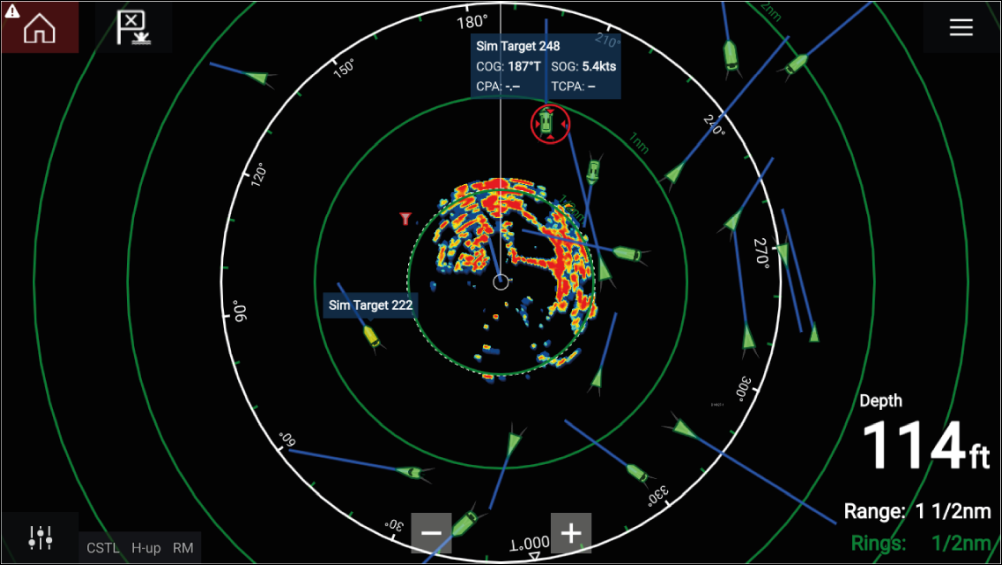
Up to 100 AIS targets can be tracked simultaneously. If more than 100 targets exist, within your range, the 100 targets nearest to your vessel will be displayed.
Target vectors and information can be displayed for each target by selecting the relevant option from the AIS target context menu. The AIS target context menu is accessed by selecting the AIS target.
You can also select the type of AIS targets that should be displayed, i.e.: All, Dangerous, Buddies and hide static targets from the AIS Settings tab.
AIS target list
The AIS target list can be accessed by selecting the AIS tab from the Targets menu: .
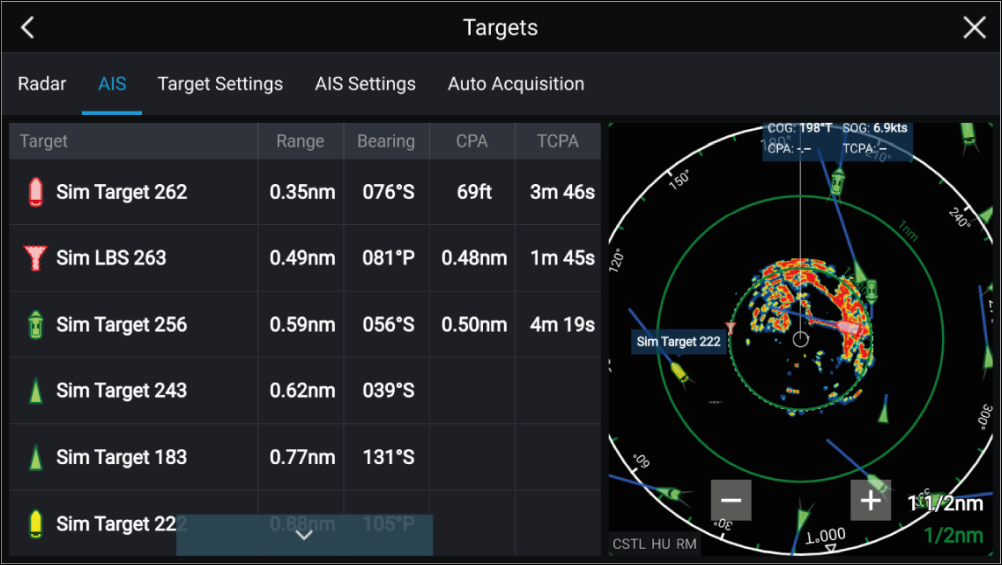
The list identifies: Target name and Range and Bearing (from your vessel). Where relevant, CPA (Closest point of approach) and TCPA (Time to Closest Point of Approach) values are also shown.
Selecting a target from the list will highlight the selected target in the LiveView pane on the right of the screen and display Pop-over options. Pop-over options enable you to View full target data or add an AIS target a buddy by selecting Add as buddy.
AIS icons used for targets marked as buddies will be filled yellow. You can also rename buddy targets or remove buddies using the Pop-over options.
AIS target symbols
You can enable enhanced AIS target symbols from the Advanced Settings menu: (). With enhanced mode enabled, the enhanced symbols are used in place of the standard vessel symbols.
Standard AIS symbols — type
|
|
Vessel |
|
SART (Search and Rescue Transponder) |
|
|
Land-based station |
|
ATON |
|
|
SAR (Search and Rescue) |
|
Virtual ATON |
|
|
* Blue Force vessel |
|
* Blue Force SAR |
| Note: * Requires STEDS-AIS hardware. |
Vessels equipped with STEDS-AIS hardware appear as Blue Force targets if:
- your MFD has a valid passphrase.
- you have received a SITREP from them within the last 6 minutes.
- their AIS mode is not set to Receive only.
If the above conditions are not met then the target icon will revert to using the standard, Green AIS target icon.
Enhanced AIS symbols — type
|
|
Sailing Vessel |
|
Commercial |
|
|
High speed vessel / Wing In Ground vessel |
|
Cargo vessel |
|
|
Passenger vessel |
|
Other |
Enhanced AIS symbols are scaled or outlined according to the reported size of the vessel, as shown below:
|
|
Relative length (Grey outline) |
AIS symbol status
|
|
Lost (No border, crossed through) |
|
Uncertain (Dashed outline) |
|
|
Buddy (Yellow fill) |
|
Dangerous and Uncertain (Dashed outline and Flashes Red) |
|
|
Dangerous (Flashes Red) |
|
ATON off position (Red border) |
AIS settings
|
Setting |
Description |
Options |
|---|---|---|
|
Show AIS targets in Chart / Show AIS targets in Radar |
Enables and disables AIS targets in the Chart and Radar apps. |
|
|
Enables and disables the display of enhanced AIS target icons. |
|
|
|
When enabled, AIS target names are permanently displayed next to the target icon. |
|
|
|
Show these AIS types |
Determines the types of AIS target displayed in the Chart and Radar apps. |
|
|
Hide static targets |
When enabled, an AIS target travelling under 2 knots will be hidden, unless it is or becomes dangerous. |
|
|
When enabled, your vessel’s AIS device will not transmit your position or details. |
|
Radar targets
Tracked radar targets are identified onscreen using target symbols.
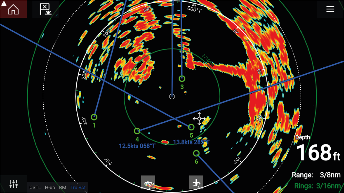
Multiple radar targets can be tracked simultaneously.
Target vectors and information can be displayed for each target.
Radar target options are available from the Radar target context menu. The Radar target context menu provides options for you to Cancel target, Show CPA graphic or display Target info onscreen by selecting the relevant option. The Radar context menu is accessed by selecting the radar target.
Radar target acquisition data source requirements
| Data type | Example data source |
|---|---|
| COG (Course Over Ground) | GPS or GNSS receiver (MFD internal receiver or external receiver). |
| SOG (Speed Over Ground) | GPS or GNSS receiver (MFD internal receiver or external receiver). |
| HDG / HDT (True Heading) | Compass or Autopilot sensor providing Fastheading data (e.g. Evolution EV-1 / EV-2). |
Radar target symbols
| Symbol | Status | Description |
|---|---|---|

|
Acquiring target — Manual | Thin dashed Green circle |

|
Acquiring target — Auto | Thick dashed Red circle, flashes until acknowledged |

|
Auto-acquired target — Unacknowledged | Red circle, flashes until acknowledged |

|
Acquired target | Green circle with Target ID |
|
Dangerous target | Red circle with Target ID, flashes until acknowledged |

|
Lost target (Target not detected for 4 Radar scans) | Gray circle with Red cross through |
Once acquired the target’s COG (Course Over Ground) and SOG (Speed Over Ground) can be displayed below the target ID.
The Target info is colored Blue if COG and SOG values are True or Orange if values are Relative. Target info will turn Red if the target becomes dangerous.
Acquiring a target manually
Automatic target acquisition
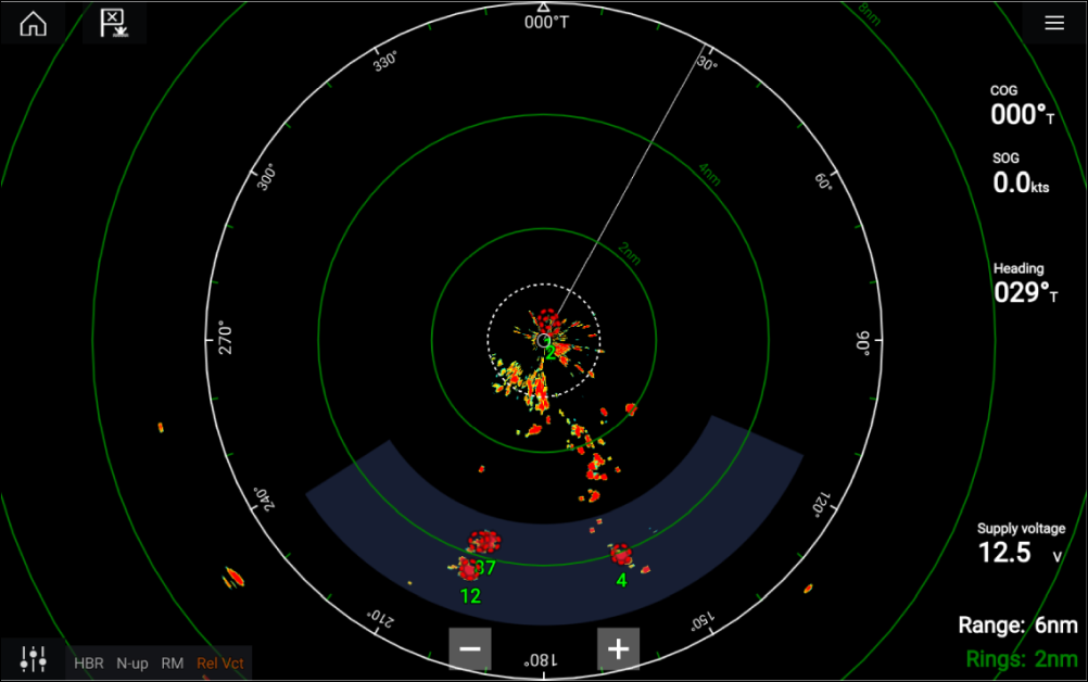
Once configured, targets which enter or appear in your chosen Guard Zone(s) will be automatically acquired.
Note:
|
Setting up automatic target acquisition
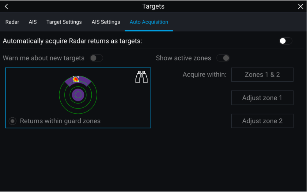
Radar target list
The AIS target list can be accessed by selecting the Radar tab from the Targets menu: .
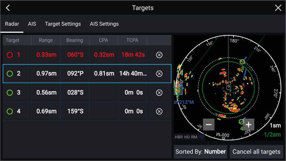
The list identifies: Target number and Range and Bearing (from your vessel). Where relevant, CPA (Closest point of approach) and TCPA (Time to Closest Point of Approach) values are also shown.
Selecting a target from the list will highlight the selected target in the LiveView pane on the right of the screen and display Pop-over options. Pop-over options enable you to Cancel target, Show CPA graphic or Display Target info by selecting the relevant option.
The Radar target list can be Sorted By: target Number or its Range from your vessel, by selecting the Sorted By: option at the bottom of the LiveView.
Radar targets can also be cancelled individually by selecting the ‘X’ next to the target’s details in the list, or you can cancel all targets by selecting Cancel all targets.
Target settings
Reference mode
Target settings can be configured to either True or Relative mode. In True mode, Trails, Vectors and History are colored Blue and are shown ground referenced (i.e. the object or target’s actual Course Over Ground (COG)). In Relative mode, Trails, Vectors and History are colored Orange and are shown relative to your vessel’s movement.
To switch the target reference mode, select the REFERENCE MODE setting. Alternatively, you can switch reference mode by selecting the onscreen Image Adjustment icon and then selecting either True or Relative.
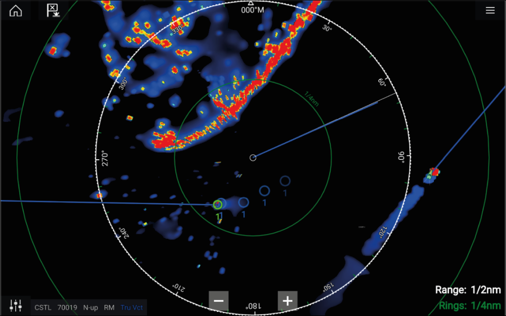
|
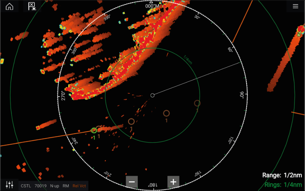
|
|
True mode |
Relative mode |
The Target Settings reference mode is independent of your vessel’s motion mode.
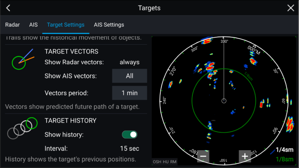
Target vectors
Target vectors show the predicted future course of a target.
Target vectors for acquired Radar targets are always shown. By default, target vectors are also shown for all AIS targets. You can switch the Show AIS vectors to Manual, enabling you to switch vectors for AIS targets On or Off for each target individually, via the target context menu.
The length of the Vector line signifies where the target will be after the time specified in Vector period has passed. The Vector period can be adjusted by selecting the current Vector period value and choosing a time from the Pop-over options.
Target history
Target history shows a target’s previous positions.
Target history can be enabled or disabled using the Show history toggle switch.
Target history is plotted by displaying a target symbol at the vessel’s position each time the value specified in the Interval setting has passed. The Interval is automatically calculated based on the target vector’s Vector period, divided by 4.
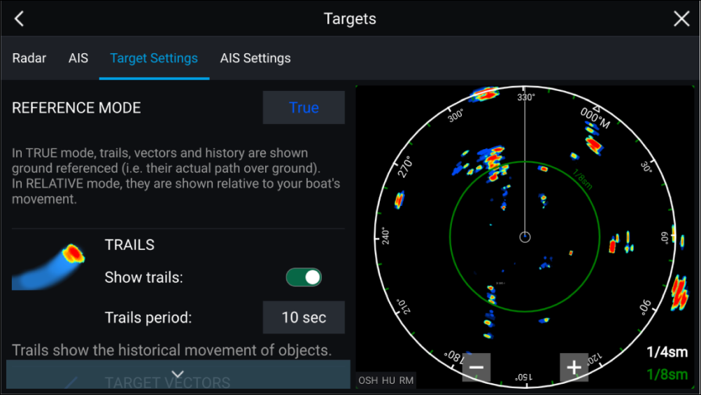
Trails
Trails plot the historical movements of objects (Radar returns) for the time specified in the Trails period setting.
Trails are subject to the selected “Reference Mode” (i.e. True, to show actual motion over “ground” (COG), or Relative, to show motion relative to your vessel).
Trails can be enabled and disabled using the Show trails toggle switch.
Historical object position is shown as a colored trail behind the object.
Onscreen target settings
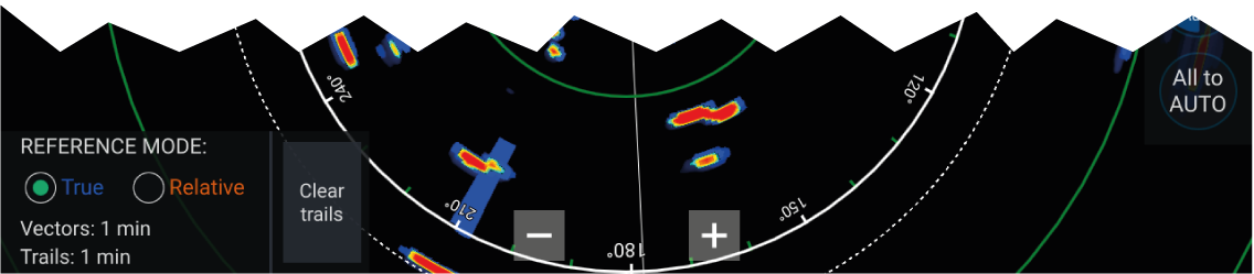
The following target settings and information is available:
Clearing / resetting trails
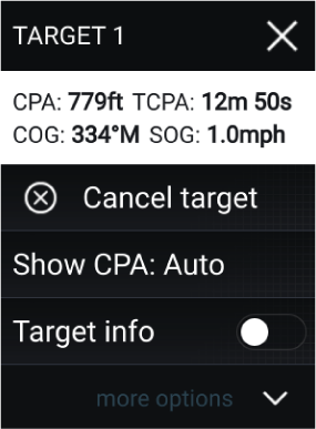
Dangerous targets alarm
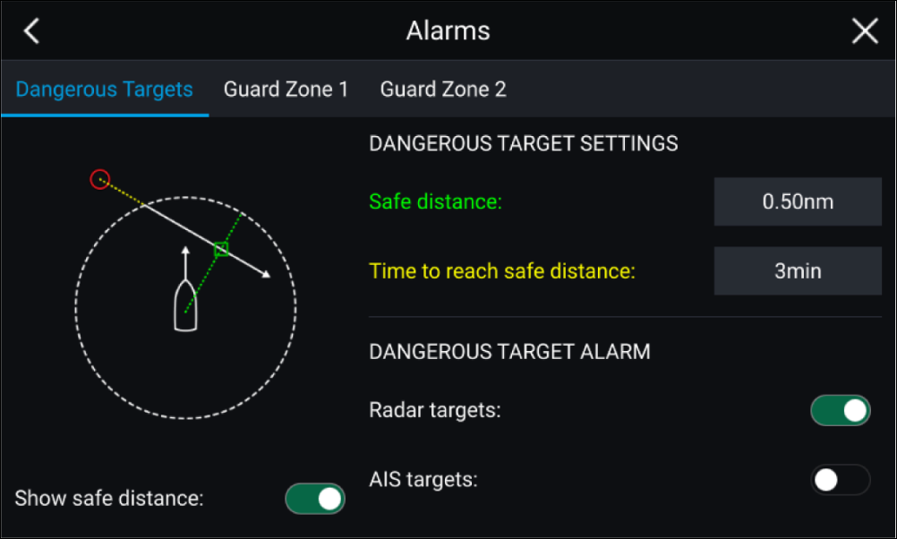
To set up the Dangerous target alarm, first adjust the Safe distance to the desired value and then select a Time to reach safe distance. The alarm will be triggered if a tracked target will reach the specified Safe distance from your vessel within the time period selected.
You can choose whether you want the Dangerous target alarm to trigger for Radar and / or AIS targets.
You can display a Safe distance ring around your vessel in the Radar app using the Show safe distance control.
Guard zone alarms
2 Guard zones can be configured for each connected Radar scanner.
The Guard zones can be configured from the Alarms menu: or
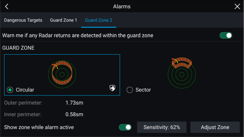
A Guard zone can be configured as a sector or as a circle around your vessel.
Selecting Adjust Zone allows you to configure the size of the Guard Zone.
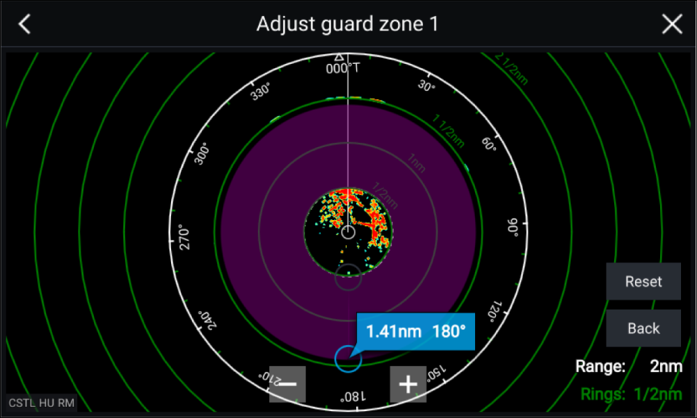
Adjust the guard zone’s size by dragging the inner and outer perimeter end points (circles) to the desired locations.
Once configure select Back.
If required, you can also adjust the Guard zone sensitivity. Sensitivity determines the size at which objects trigger the alarm.
Doppler Radar overview
Typically Doppler Radar works best with objects that are moving directly towards or away from the vessel. Doppler Radar can highlight only those targets that are moving relative to the vessel (e.g. other boats, but not land or buoys, for example).
Doppler Radar works by transmitting a microwave signal which is then reflected off a desired moving target at a distance. By analyzing how the object's motion has altered the frequency of the returned signal, the Doppler Radar can interpret the variation to provide highly accurate measurements of a target's direction of travel, relative to the Radar scanner.
Doppler Radar technology is particularly beneficial in a marine environment, where poor weather conditions and visibility can make target tracking difficult. Additionally, it is not always easy to interpret the information displayed by traditional Radar technology. With the integration of Doppler information, the process of matching on-screen radar returns with real-world objects becomes a much simpler task.
Doppler mode
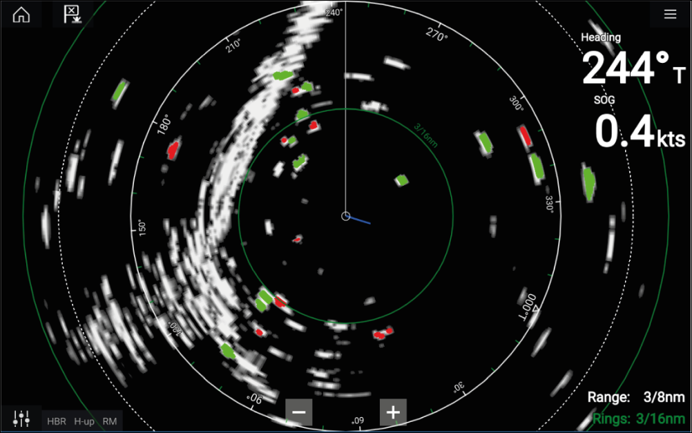
Doppler mode — Enabling and disabling
Doppler mode is enabled from the Main menu: .
With Doppler mode enabled the color palette will change to the default Doppler palette, all approaching targets will be colored Red and all targets moving away from you will be colored Green.
Doppler mode is suspended at ranges of 12 nm and greater. The Radar color palette will remain the same but targets will not be highlighted.
Doppler mode — Color palettes
Doppler has unique color palettes which help to ensure the Red and Green Doppler targets stand out from the Radar image. When Doppler is enabled the standard color palette setting will show only the unique Doppler color palettes: Doppler grey, Doppler blue and Doppler yellow.
The Color palettes can be selected from the Presentation tab: .
Doppler data source requirements
Required data sources
|
Data type |
Example data source |
|---|---|
|
COG (Course Over Ground) |
GPS or GNSS receiver (MFD internal receiver or external receiver). |
|
SOG (Speed Over Ground) |
GPS or GNSS receiver (MFD internal receiver or external receiver). |
Recommended data source
|
Data type |
Example data source |
|---|---|
|
HDG / HDT (True Heading) |
Compass or Autopilot sensor providing Fastheading data (e.g. Evolution EV-1 / EV-2). |
|
Note:
A Heading data source is not essential for Doppler operation. However it will improve the performance of Doppler mode at slower speeds (< 15 knots), when tide set and leeway are present. |
Blank sectors
|
Note:
Sector blanking is only compatible with Magnum Open Array radar scanners. |
Blank sectors can be enabled from the Radar app settings:
Two blank sectors can be enabled. You can edit the minimum and maximum limits of each blank sector; this will determine how much of the radar display is hidden.
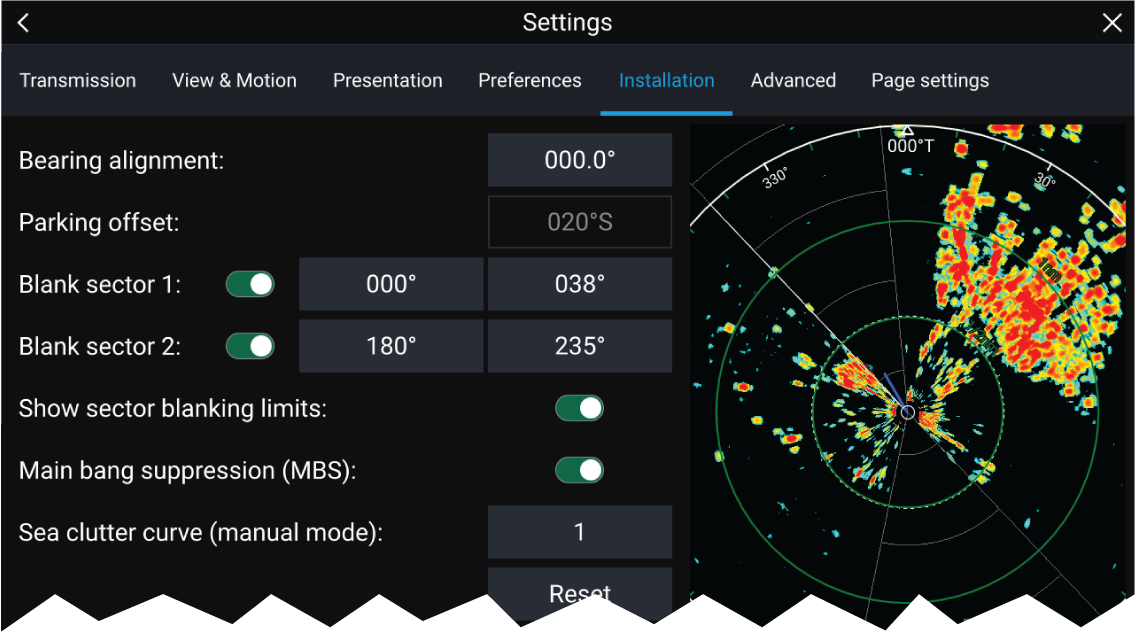
Blank sectors can be enabled / disabled on the radar overlay in the Chart app:
For more information refer to Radar settings
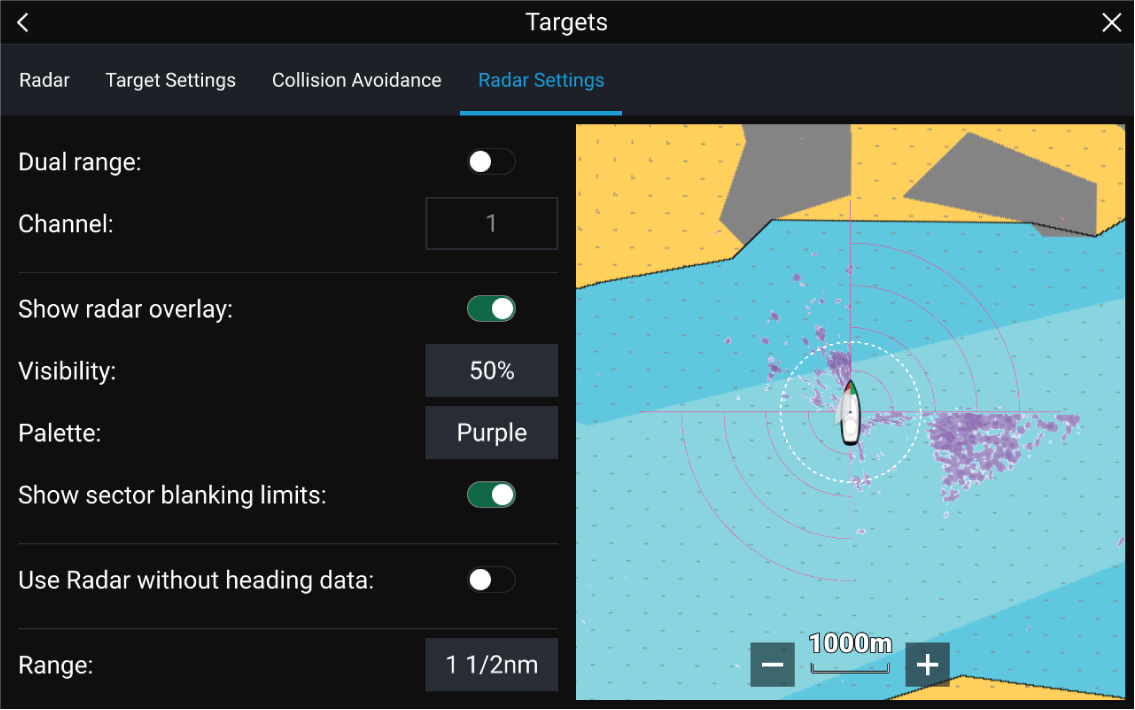
Radar sensitivity controls
The Sensitivity controls available are dependant upon the Radar scanner in use.
| Control | Name | Description |
|---|---|---|
|
|
‘G’ Gain |
The control determines the signal strength at which target returns are shown onscreen. The Gain control can be set to Auto or Manual. A higher value produces more target returns and noise onscreen. |
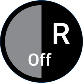
|
‘R’ Rain |
Precipitation appears on the Radar screen as lots of small echoes which continuously change size, intensity and position. The Rain control suppresses these echoes making it easier to identify real object. The higher the Rain control is set the more echoes will be suppressed. |
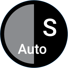
|
‘S’ Sea |
Radar echoes from waves can clutter the Radar screen. The Sea control suppresses these echoes (for up to 5 nm depending on conditions) making it easier to identify real objects. The higher the Sea control is set the more echoes will be suppressed. |

|
‘CG’ Color Gain |
The control sets the lower limit for the color used for the strongest target returns. All target returns above this value are displayed in the strongest color. Those with a weaker value are divided equally between the remaining colors. The control can be set to Auto or Manual. |
|
|
All to Auto |
Sets all Sensitivity settings to Auto with 0% offset. |
Radar settings
Transmission tab
|
Settings |
Description |
Options |
|---|---|---|
|
Scanner |
Allows you to select the Radar scanner that you want to use. |
List of available Radar scanners. |
|
Dual range |
Enables and Disables dual range. |
|
|
Channel |
Determines which channel is shown in the Radar app. |
|
|
Antenna size selection |
Open Array Radar antenna size selection. |
|
|
Timed transmit |
Enables and disables Timed transmit. Timed transmit configures your Radar to transmit at periodic intervals to conserve power. |
|
|
Standby |
Determines the length of time the Radar is in Standby for in Time transmit mode. |
|
|
Transmit |
Determines the amount of scans the Radar will perform when transmitting in Time transmit mode.. |
|
View & Motion tab
|
Settings |
Description |
Options |
|---|---|---|
|
Orientation |
Head-up The top of the screen always points towards your vessel’s current heading and as your heading changes the Radar image rotates accordingly. In Head-up the motion mode is fixed to Relative motion. North-up The top of the screen always points towards north and as your vessel’s heading changes the SHM rotates accordingly. Course-up In Course-up the top of the screen always points towards your destination and as your heading changes the SHM rotates accordingly. |
|
|
Motion mode |
Relative motion The position of your vessel remains fixed onscreen and the Radar image moves relative to your position. In Relative motion mode you can adjust your vessel’s onscreen position using the Boat position setting. True motion Stationary Radar targets remain fixed and moving targets, including your vessel, move in true perspective to each other and to landmass. As your vessel’s position reaches the edge of the screen, the image is redrawn to reveal the area ahead. In True motion mode the boat position is fixed to Full offset. |
|
|
Boat position |
The boat position determines the position of your vessel onscreen. You can adjust the Boat position to provide a greater distance ahead of your vessel. Your boat position can only be changed in Relative motion mode. |
|
Presentation tab
|
Settings |
Description |
Options |
|---|---|---|
|
Range rings |
Enables and disables Range rings in the Radar app. |
|
|
Range ring labels |
Enables and disables Range ring distance labels in the Radar app. |
|
|
Color palette |
Allows selection of the color palette. |
List of color palettes. |
Preferences tab
|
Settings |
Description |
Options |
|---|---|---|
|
VRM/EBL reference |
Determines the reference point used for VRM/EBLs. |
|
|
Interference rejection |
Suppresses interference from other close by Radar scanners. |
|
|
Interference rejection level |
Determines the level of suppression used. Only available when Interference rejection is enabled. |
Quantum ™
Non-HD Digital Radomes
|
|
Target expansion |
When enabled, increases the Radar pulse length to provide larger target returns. |
|
|
Expansion level |
Determines the level of expansion used. Only available when Target expansion is enabled. |
|
|
Tune adjust |
Allows you to adjust the Radar scanners receiver for maximum target returns. It is recommended that the Radar scanner is allowed to warm up for at least 10 minutes prior to making adjustments. |
|
|
Radar speed |
Allows you to select the appropriate rotation speed for your range. The Auto option provides an increased refresh rate at Radar ranges up to 3 nm. |
|
|
Transmit frequency |
Changing the Transmit frequency can reduce interference on the Radar image. |
|
Installation tab
Under normal circumstances it should not be necessary to adjust Installation settings.
|
Settings |
Description |
Options |
|
|---|---|---|---|
|
Bearing alignment |
Enables you to align the Radar image correctly in relation to your vessel’s bow. |
|
|
|
Parking offset |
Allows you to select the “parked” position of your Open Array’s antenna. This feature is only available when the Open Array radar scanner is in Standby. |
|
|
|
Blank sector 1 |
Allows you to hide a specific section of the radar display, creating a “blank” sector onscreen that shows no radar signal returns.
|
|
|
|
Blank sector 2 |
Allows you to hide an additional section of the radar display, creating a “blank” sector onscreen that shows no radar signal returns.
|
|
|
|
Main Bang Suppression (MBS) |
MBS eliminates saturation immediately around your vessel. When adjusting Zero range it is recommended that MBS is set to Off. |
|
|
|
Sea clutter curve |
Adjusts the Radar scanner’s sensitivity to Sea clutter. |
|
Advanced tab
Under normal circumstances it should not be necessary to adjust Advanced settings.
|
Settings |
Description |
Options |
|---|---|---|
|
Tune preset |
Radar tuning is controlled either automatically or manually, using the Tune adjust setting. Tune preset controls the range available to the Tune adjust control. |
|
|
STC preset |
The Sensitivity Time Control (STC) can be used to equalize targets across the image. If you find targets are brighter or dimmer nearer the center of the image adjust the STC preset until the desired result is achieved. |
|
|
Zero range |
Zero range (Display timing) is used to configure the zero range of the Radar scanner so that objects appear at the correct distance. |
|
|
Reset |
Resets Installation and advanced settings to factory defaults. |
|
Page settings tab
|
Settings |
Description |
|---|---|
|
Data Overlays |
Enables configuration of Data overlays |
|
Edit split ratio |
Enables you to customize the position of the partitions in splitscreen app pages. |
Dashboard app
Dashboard app overview
| Note: For data to be available in the Dashboard app it must be transmitted to your MFD from compatible hardware using supported protocols and messages. |
The Dashboard app can be displayed in Fullscreen and half screen portrait app pages.
For each instance of the Dashboard app you can select which Data pages you want to use, the Data page selection will persist over a power cycle.
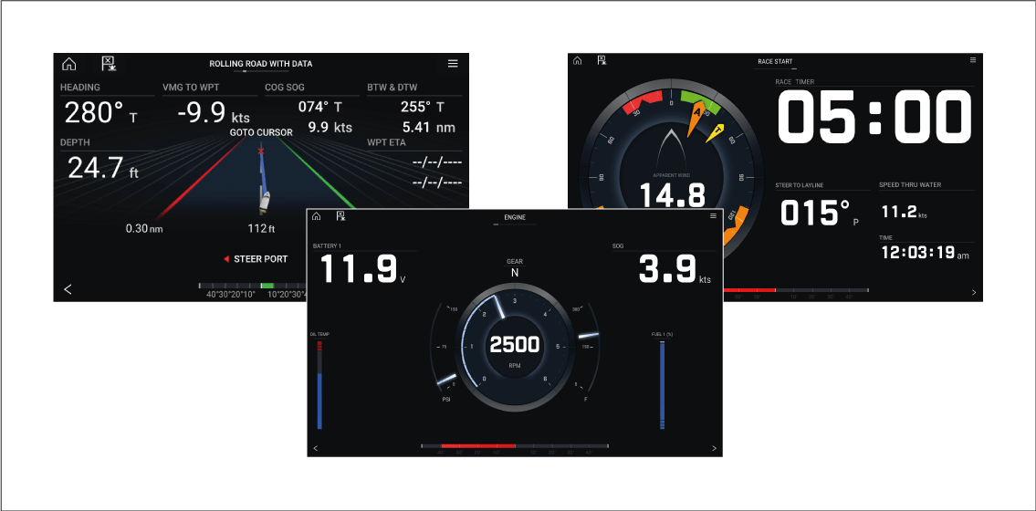
The Dashboard app is pre-configured with a number of customizable data pages.
Dashboard app controls


Switching data page
Selecting Data pages to display
The selected page will no longer be available in the current instance of the Dashboard app.
Selecting Show page for a hidden page will include the page in the app instance again.
Default data pages
- Engines
- Sailing (only shown if boating activity is set to Sailing in startup wizard)
- Race start (only shown if boating activity is set to Sailing in startup wizard)
- Navigation
- Rolling road with data
- Tanks
- Bidata
- Single data
- Fuel
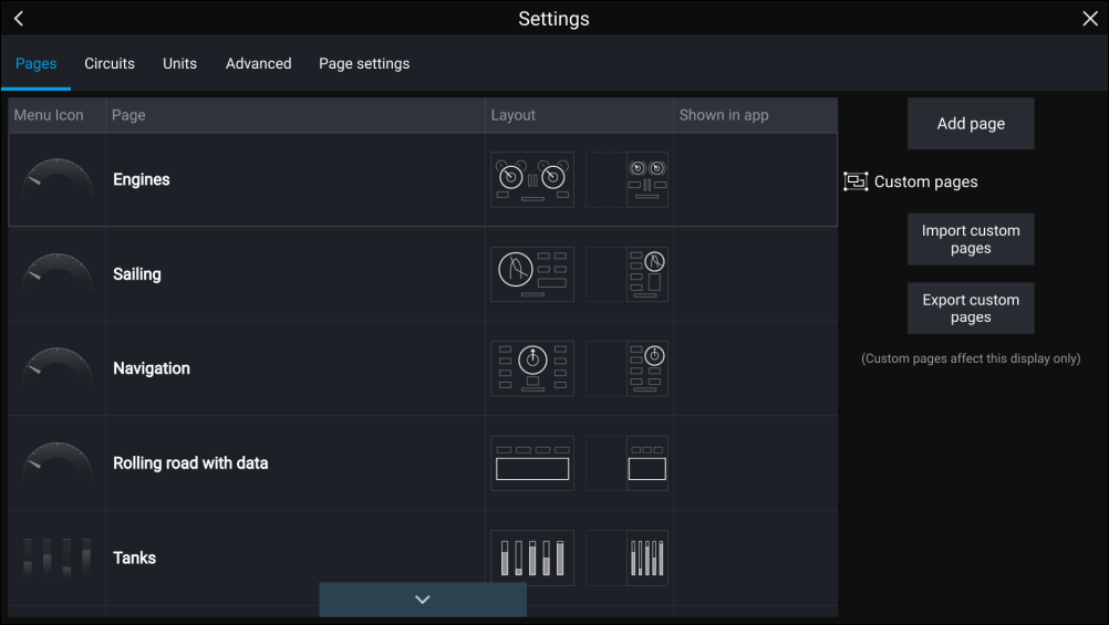
The displayed data items on each of these pages can be customized.
Customizing existing Data pages
Alternatively you can select Customize page from the app menu: .
Available data items
|
Data type |
Data item |
Notes |
|---|---|---|
|
|
|
|
||
|
||
|
|
|
|
|
|
|
For tanks 1 to 5:
For All tanks:
|
|
|
|
||
|
||
|
|
|
|
||
|
|
|
|
|
|
|
Dashboard settings menu
Pages tab
The Pages tab provides a list of all available pages.
| Settings | Description | Options | |
|---|---|---|---|
|
Page list |
Pop-over options allow you to customize the Dashboard app. You can rearrange pages, add new pages, rename existing pages or reset pages to default settings.
|
|
|
|
Add page |
You can add new dashboard pages that you can customize by selecting Add page. |
Displays pop-over with page layouts. |
|
|
Import custom pages |
You can import digital switching pages . Please refer to Raymarine Product support for more details. |
Displays file browser |
|
|
Export custom pages |
You can export your digital switching pages so that they can be restored at a later date. You must use this feature if you wish to export or backup your digital switching pages, as digital switching pages are not included in the standard MFD “Backup and restore” process, which is used to backup user settings only. Please refer to Raymarine Product support for more details. Exporting digital switching pages must be performed on each MFD configuration. |
Save dialog |
Circuits tab
| Settings | Description | Options |
|---|---|---|
|
List of tripped channels |
In Digital Switching systems, the circuit tab provides a list of tripped channels. Tripped circuits can be acknowledged and reset from the pop-over options. |
|
Units tab
| Measurement | Units |
|---|---|
|
Distance units |
|
|
Speed units |
|
|
Depth units |
|
|
Temperature units |
|
|
Date format |
|
|
Volume units |
|
|
Economy units |
|
|
Wind speed units |
|
|
Pressure units |
|
|
Time format |
|
| Settings | Description | Options |
|---|---|---|
|
Bearing mode |
Determines how bearing and heading data is displayed. |
|
|
System Datum |
Determines the datum used by your MFD. This should be set to the same datum used by your paper charts. |
List of available datums. |
|
Variation |
When set to Auto the MFD will automatically compensate for the naturally-occurring offset of the Earth’s magnetic field. |
|
|
Manual variation |
When variation is set to Manual, you can specify an offset. |
|
Advanced tab
| Settings | Description | Options |
|---|---|---|
|
Maximum RPM |
You can select a maximum RPM for your engine dials, or allow the system to automatically configure the Maximum RPM. |
|
|
Custom RPM Red zone |
You can create a custom Red zone for your RPM dials. |
|
|
Wind angle response |
You can configure the rate at which Wind angle data is updated on the MFD. The Higher the response setting the faster the update rate will be. |
|
|
Wind speed response |
You can configure the rate at which Wind speed data is updated on the MFD. The Higher the response setting the faster the update rate will be. |
|
Page settings tab
| Settings | Description |
|---|---|
|
Data Overlays |
Enables configuration of Data overlays |
|
Edit split ratio |
Enables you to customize the position of the partitions in splitscreen app pages. |
Navigation and Sailing dials
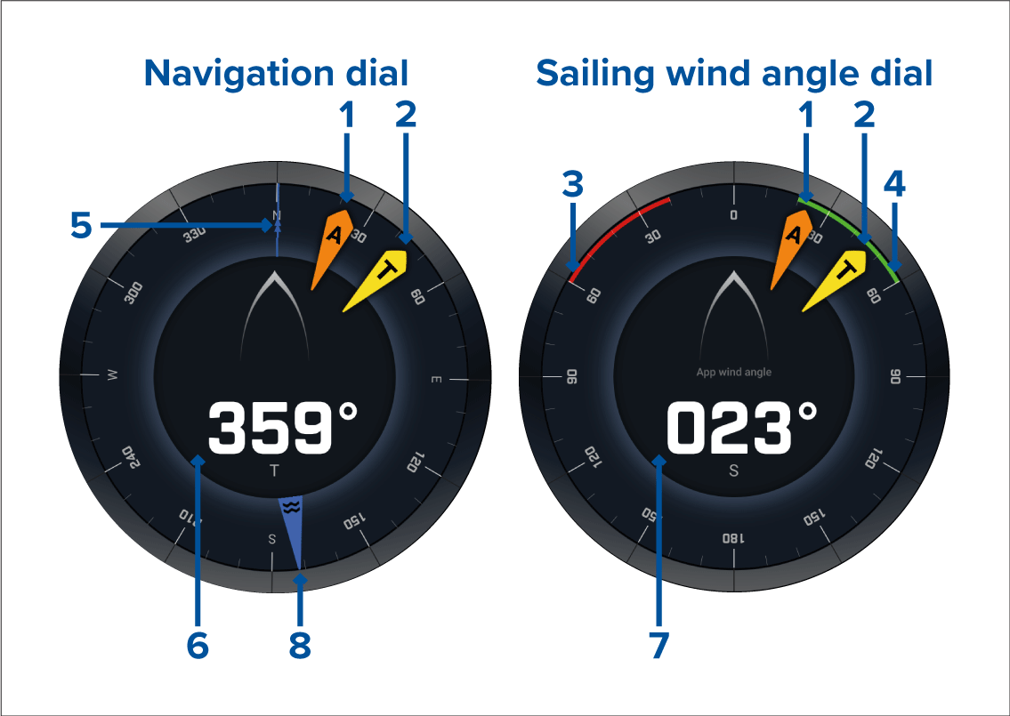
- Apparent Wind Angle (AWA) indicator
- True Wind Direction (TWD) indicator
- Port closed hauled angle
- Starboard closed hauled angle
- Compass
- Heading
- Apparent Wind Angle (AWA)
- Tide direction indicator
Sailing dials for laylines
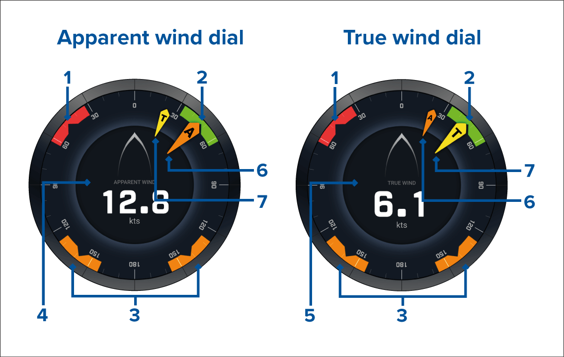
- Port wind angle target
- Starboard wind angle target
- Downwind wind angle target
- Apparent wind speed (AWS)
- True wind speed (TWS)
- Apparent Wind Angle (AWA)
- True Wind Angle (TWA)
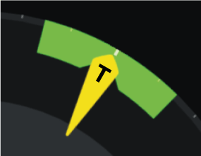
Sailing data items
- Apparent wind sailing dial
- Distance to tack
- Time to tack
- Sailing distance to waypoint
- Waypoint sailing Time To Go
- Speed through water
- Target speed through water
- Steer to layline
- Polar performance (only active with sailing profile set to polar)
- Rudder bar
It is advised to use the Sailing data items in combination with the Laylines feature available in the Chart app. For more information refer to: Laylines
Race Start data items
|
Note:
Lighthouse software version 3.10 is required. |
- Apparent wind sailing dial
- Race Timer (can be used to start, stop and edit the countdown timer)
- Distance to line
- Line bias
- Time to burn
- Time
It is advised to use the Race Start data items in combination with the Laylines feature and the Race Start Line and Race Timer features available in the Chart app. For more information refer to:
Race Start Line (SmartStart) and Race Timer
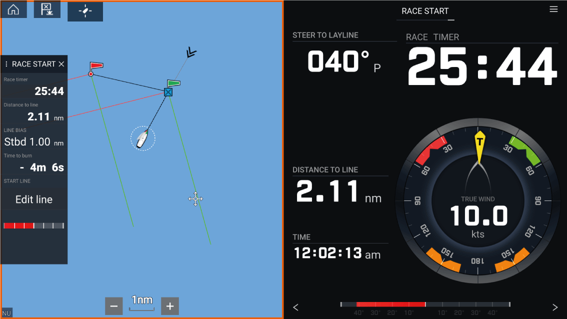
Yamaha app
Yamaha engine gateway selection
Engine gateway selection is performed as part of the Boat details settings in the initial MFD start up wizard. The selection can also be changed in the Boat details settings tab: .
- If you have a compatible gateway interface, select Yamaha from the Engine manufacturer options.
- If you have a compatible gateway that includes the Yamaha MFD HDMI interface, select Yamaha HDMI from the Engine manufacturer options.
Compatible Yamaha gateways
- The Yamaha app is compatible with Yamaha Command Link and Command Link Pro when connected to the MFD via a Yamaha NMEA 2000 gateway or CL7 gauge.
- The Yamaha HDMI app is compatible with Yamaha Command Link and Command Link Pro when connected to the MFD via a Yamaha Helm Master EX 6YG gateway and MFD interface (MFDI).
Yamaha HDMI overview
Yamaha app overview
Note:
|
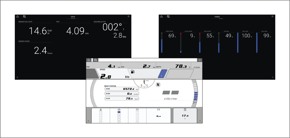
Requirements
- A compatible Yamaha Command Link or Command Link Pro network is connected to the MFD via a Yamaha NMEA 2000 gateway (6YG-8A2D0-00-00) or CL7 Gauge.
- Your MFD must be running LightHouse 3 version 3.9 or above.
|
Note:
Do not use a Gateway module (6YG-8A2D0-00-00) and CL7 Gauge together on the same network. |
Yamaha app controls
Switching data page
Customizing Data pages
Available data items
Engine page
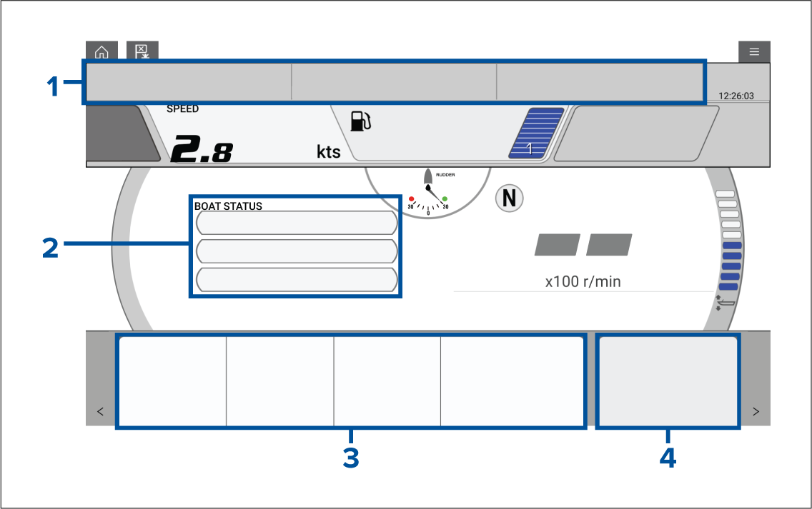
|
Cell 1 and Cell 2 |
|||
|
Data type |
Data item |
Data type |
Data item |
|
|
Environment |
|
|
|
|
GPS |
|
|
|
|
Pilot |
|
|
|
|
Speed |
|
|
|
Cell 3 |
Cell 4 |
||
|
Data type |
Data item |
Data type |
Data item |
|
|
Boat |
|
|
Data Page
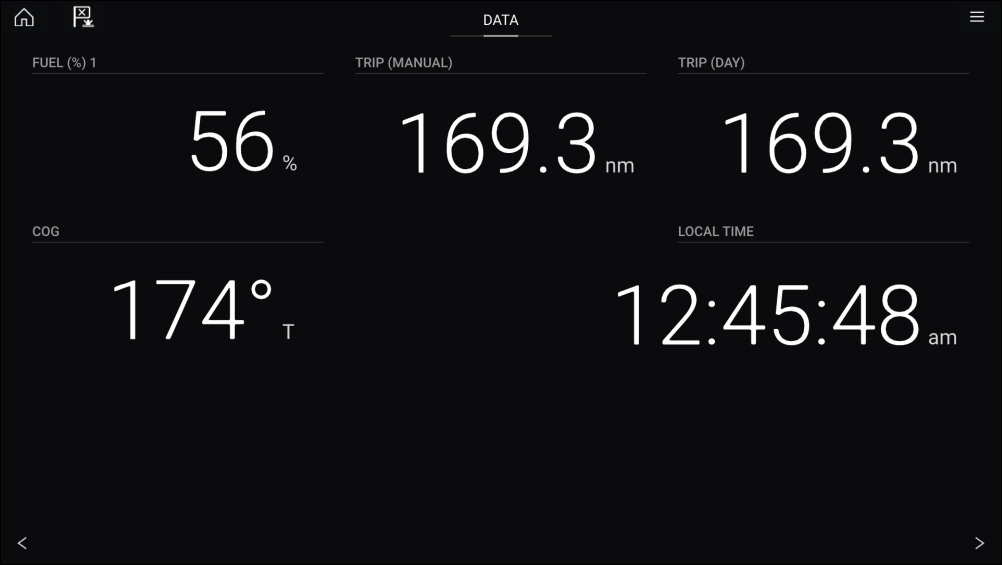
|
Data type |
Data item |
Data type |
Data item |
|
GPS |
|
|
|
|
Heading |
|
|
|
|
Navigation |
|
|
|
|
Pilot |
|
|
|
|
Speed |
|
|
|
|
Time |
|
|
|
|
Wind |
|
Tanks Page
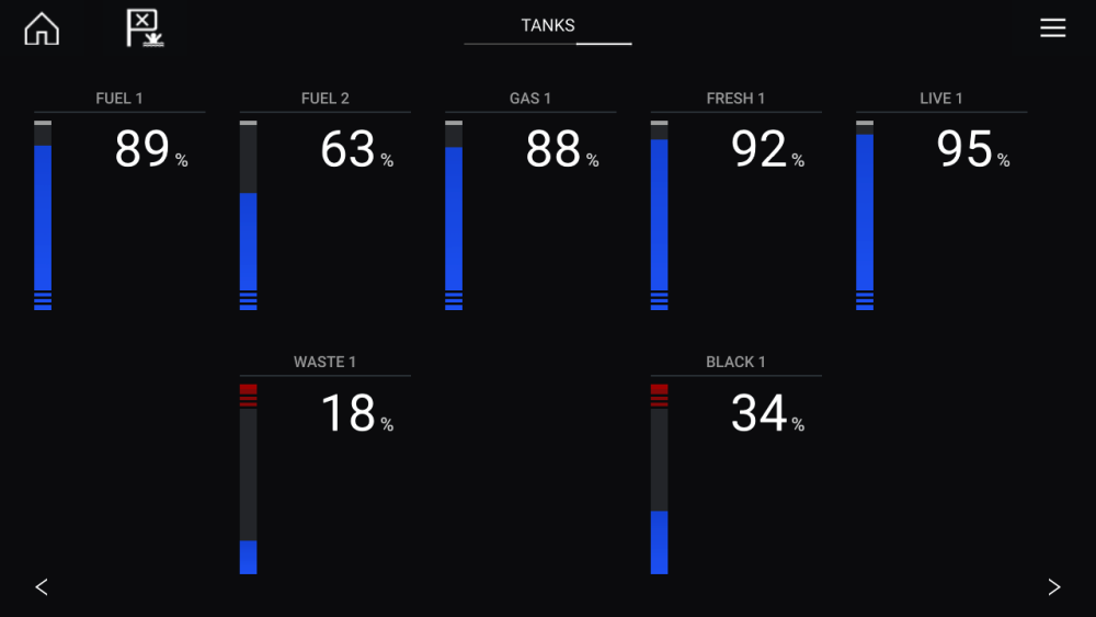
Engine page
- Rudder position (single engine only)
- Transmission
- Speed
- Revolutions Per Minute (r/min)
- Engine trim
- Number of fuel tanks and fill level
Troll mode can also be enabled from this page.
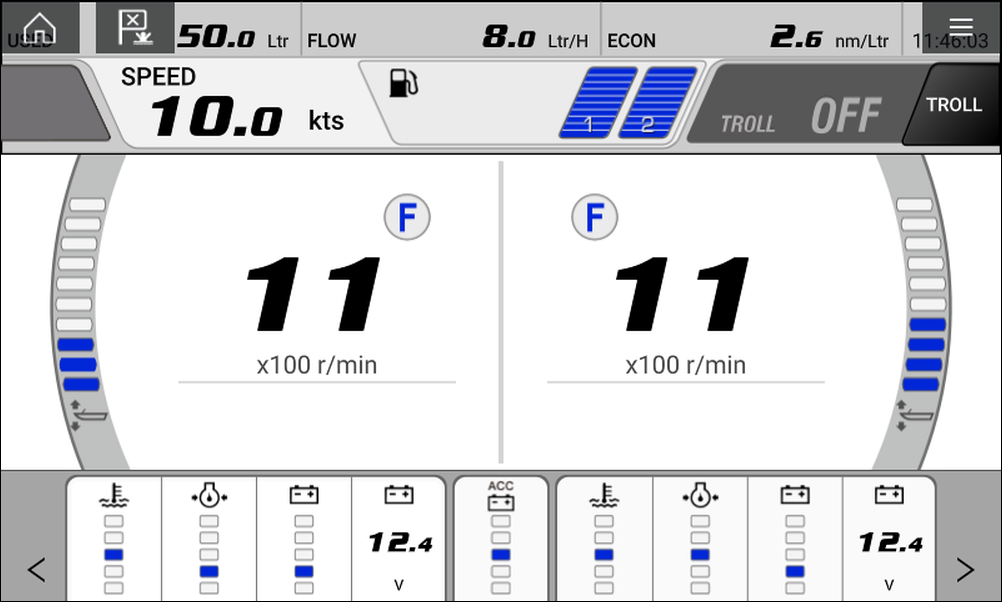
Engines
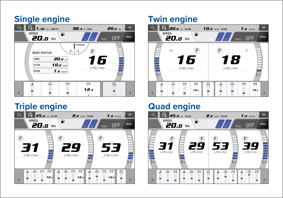
The number of engines and their manufacturer can be set on the Boat details page.
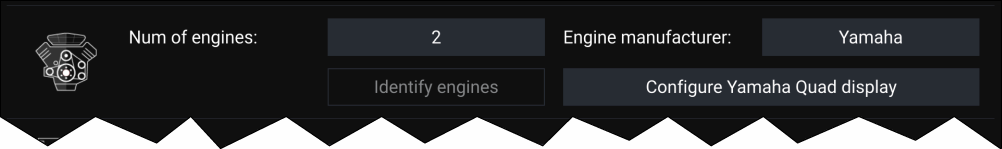
If your vessel is setup using the old quad engine system (2 MFDs for Port and Starboard Engines), you can select which engines are displayed per MFD by selecting Configure Yamaha Quad display and choosing Port side or Starboard side.
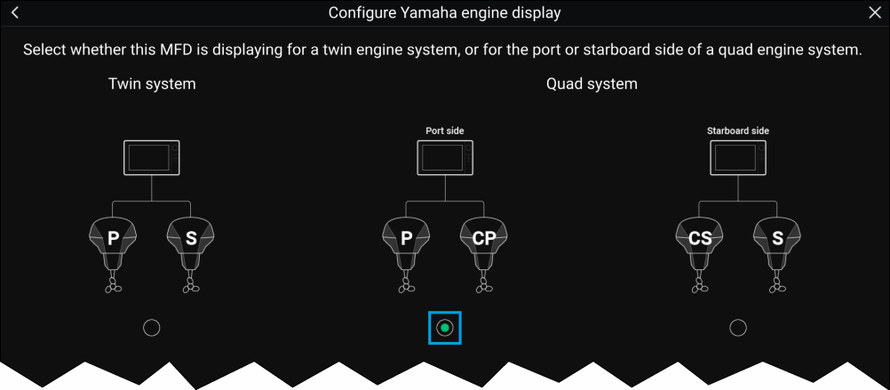
The engine page will update to reflect which engines your MFD is networked to, with Port and Central Port symbols or Starboard and Central Starboard symbols.
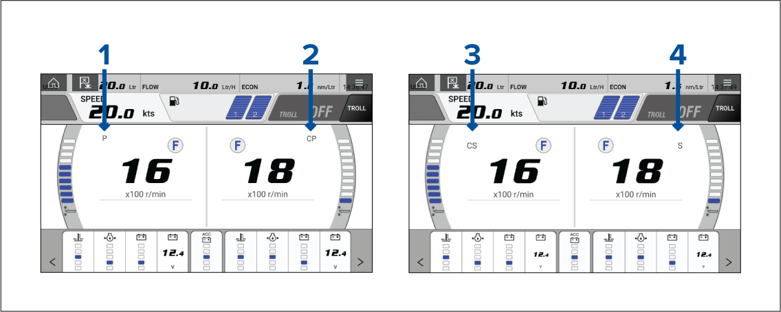
- Port engine
- Central Port engine
- Central Starboard engine
- Starboard engine
Transmission
The transmission icons indicate which transmission mode your vessel’s engine is currently in:
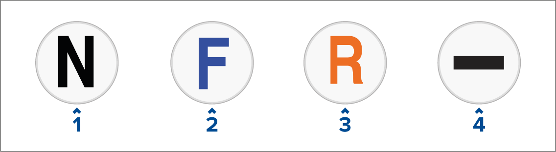
- Neutral
- Forward
- Reverse
- No transmission data detected
|
Note:
If no transmission information is detected from the CAN bus after 3 seconds, it will timeout. Ensure that your engine(s) are compatible and have been connected to your MFD network correctly. |
Status and warning indicators
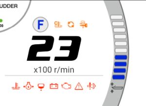
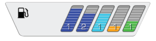
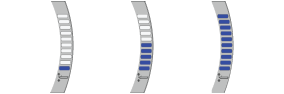

Settings
Fault codes
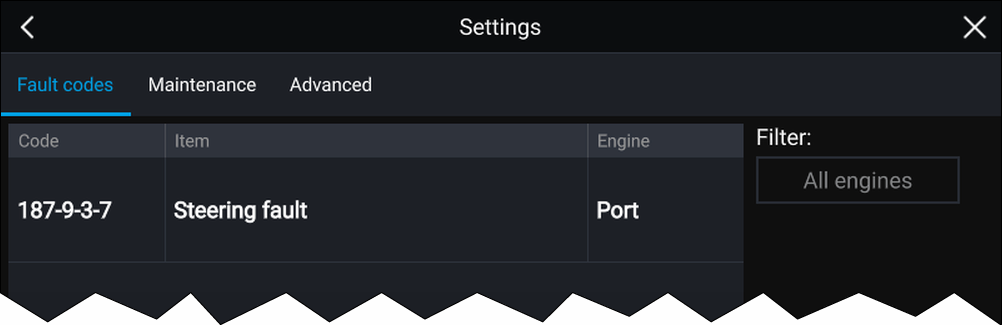
Note:
|
Maintenance
The amount of hours since last service will automatically accumulate when your Yamaha engine(s) are running. When your engine(s) have been serviced you can long hold the row and select Reset from the pop up to return the amount of hours back to 0.
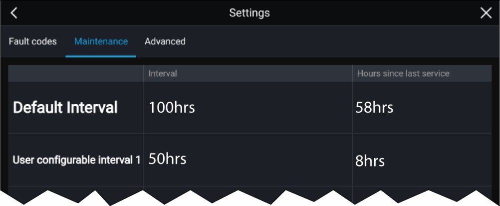
Note:
|
Advanced
Options:
Gateway reset — System protocol information reset.
Engine instances reset — Engine instances reset. Engine(s) will be reordered based on engine position:
|
Engine |
Port |
Central or Central Port |
Central Starboard |
Starboard |
|---|---|---|---|---|
|
Single Engine |
0 |
- |
- |
- |
|
Twin Engine |
0 |
- |
- |
1 |
|
Triple Engine |
0 |
1 |
- |
2 |
|
Quad Engine |
0 |
1 |
2 |
3 |
All pages reset — All data items on each data page are reset to default.
Fuel flow offset — Set the Fuel flow offset value in accordance with your Fuel flow gauge reading.
Trim Calibration — Calibrate your engine trim by pressing Set to zero if any number other than 0 is showing on the Trim Position when engine(s) have stopped.
Video app
Video app overview
Up to 4 video feeds can be displayed simultaneously when using a splitscreen app page.
Axiom ™ Pro MFDs will transmit a connected analog video feed over RayNet to enable the feed to be viewed on networked MFDs.
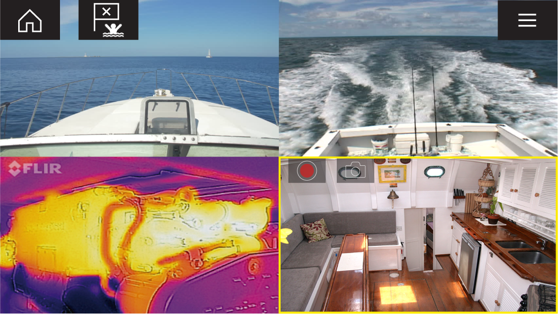
Video app pages
Each Video app instance is unique, this means that once you have selected a feed to display in a Video app page then your feed selection is saved and the same feed will be displayed whenever that app page icon is opened from the Homescreen. If you open the same Video app page from a networked MFD, the same feed will be displayed on each MFD.
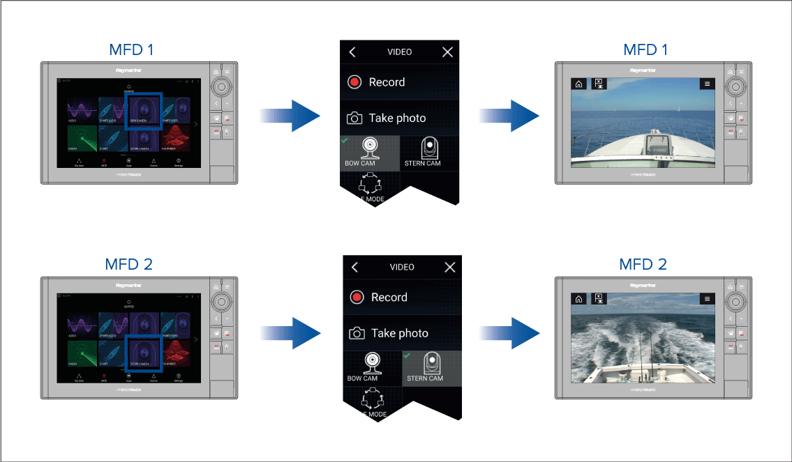
You can create additional Video app pages and assign a different feed to each. This will allow you to view multiple feeds on multiple networked MFDs simultaneously.
For example, if you want to display a different video feed on different networked MFDs, you must first create additional Video app pages.
|
Note:
When you have multiple Video app page icons on your Homescreen, you may wish to rename each icon to help you easily identify the feeds(s) assigned to each app page. For information on how to rename Homescreen icons, refer to: Creating / Customizing an App page |
Renaming video feeds
Video app controls
| Icon | Description | Function |
|---|---|---|
|
|
Home icon |
Takes you to the Homescreen |
|
|
Waypoint / MOB |
Place waypoint / activate Man overboard (MOB) alarm |
|
|
Pilot icon |
Opens and closes the Pilot Sidebar |
|
|
Menu icon |
Opens the app menu |

|
Record |
Start recording (Replaced by Stop icon whilst recording.) |
|
Stop |
Stop recording (Replaced Record icon when not recording.) |

|
Take photo |
Take a photo of what is currently displayed in the active feed. |
Pan, Tilt, Zoom (PTZ) camera controls
Swiping your finger across the screen to pan or tilt the camera.
Use Pinch-to-Zoom to zoom in and out.
When not in use place the camera in the Parked position by selecting Park camera from the menu:
Select Home from the menu: to move the camera to its Home position.
Opening the Video app
Pre-requisites:
- Ensure your video feed is compatible by checking the latest details available on the Raymarine website against your device’s specification. If in doubt please contact an authorized Raymarine dealer for advice.
- Ensure you have installed your video device in accordance with the documentation that was supplied with your device.
The Video app will open in 1 of 3 states:
| Note: If the Video app is opened soon after powering on your system, you may have to wait for the device(s) to finish booting before the video feed is displayed. |
Video feed displayed
If your device is powered up and operational then the Device’s video feed is displayed.
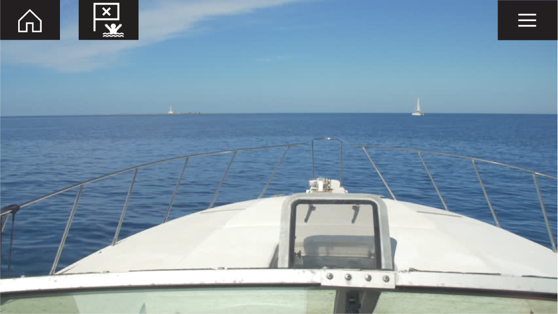
Camera not yet available
The ‘Camera not yet available’ message is displayed if:
- a Video app page is opened before the camera has finished booting up.
- connection to the camera is lost.
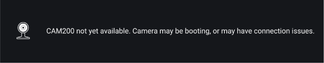
If the ‘Camera not yet available’ message is displayed for more than 2 minutes, then your MFD cannot connect to your camera. Ensure network and power connections to your camera and MFD are correct and free from damage and then power cycle your system. If the camera feed is still not displayed, refer to your equipment’s installation documentation for further troubleshooting information.
No camera detected
The ‘No camera detected’ message is displayed if:
- a Video app page is opened for the first time and no compatible camera is connected.
- a Video app page is opened for the first time before the camera has finished booting up.

If the ‘No camera detected’ message is displayed for more than 2 minutes, then your MFD cannot connect to your camera. Ensure network and power connections to your camera and MFD are correct and free from damage and then power cycle your system. If the camera feed is still not displayed, refer to your equipment’s installation documentation for further troubleshooting information.
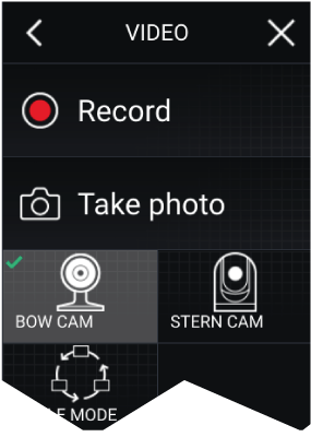
Dual streaming
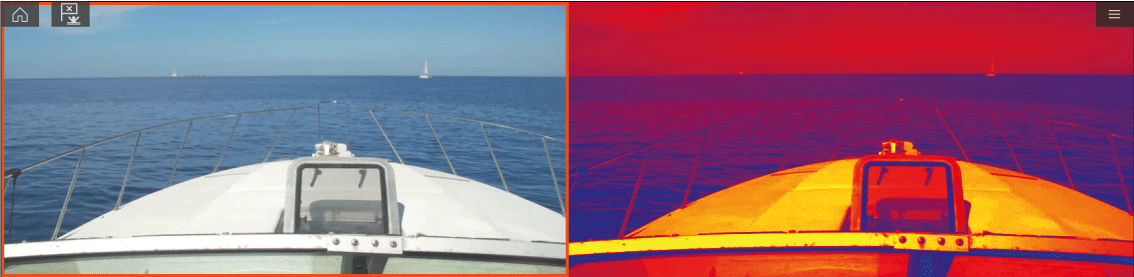
|
Note:
Dual streaming requires:
|
Single MFD
Dual MFDs
|
Note:
Make sure your MFDs are both correctly connected on the same network as the dual payload camera. |
Video app settings
Image tab
|
Settings |
Description |
Options |
|---|---|---|
|
Active feed |
On cameras with more than 1 payload you can select which feed to display in the Video app. |
|
|
Blending Mode |
On cameras with more than 1 payload you can blend the two feeds together, displaying an overlap of daylight stream on top of thermal image, providing enhanced detail.
|
|
|
Blending Level |
Set the percentage of the blend between both camera feeds for CTV or MSX blending. |
|
|
Light |
For cameras that include a light this setting switches the camera’s light on and off as well as flashing mode and SOS mode. |
|
|
Palette |
Various color palettes are available to suit different conditions or your personal preference. |
|
|
Scene |
Scene presets that have been optimized for different running conditions. |
|
|
Auto focus |
The camera will focus the image. |
|
|
Low light mode |
Visible cameras supporting low light mode can set this during low light conditions. |
|
|
Wide Dynamic Range |
Improves the viewable range of darkness to lightness of the image. |
|
|
Contrast Enhancement |
Adjusts the brightness and contrast of the image to make dark and bright sections more distinguishable. |
|
|
Electronic stabilization |
Stabilizes the image to reduce blurring caused by camera shake. |
|
|
Digital Zoom |
Zooms the camera feed to maximum. |
|
|
Roll correction (Requires AR200) |
Accounts for boat tilting and will adjust video feed accordingly. Video feed horizon will be parallel with the actual horizon. |
|
Camera setup tab
|
Settings |
Description |
Options |
|---|---|---|
|
Heater |
Enables and disables the camera’s built-in heater used to de-mist the camera lens. |
|
|
Zoom Lock |
Synchronise zoom level between visible and thermal camera feeds. |
|
|
Mirrored view |
Flips the camera image to provide a mirror image, suitable for rear view installations. |
|
|
Camera name |
Change your camera name. |
|
|
Icon |
Select the icon to be used for the camera. |
|
|
Flip image vertical |
Flips the camera image upside down, suitable for Ball-down installations. |
|
|
UI language |
Select the language of the user interface. |
|
|
On-screen icons |
Sets the level for the camera’s built-in onscreen icons |
|
|
Save default settings |
Save the current camera settings as the default. |
|
|
Restore default settings |
Restore the camera settings to default. |
|
|
Self-tests and calibration |
Offers a series of tests and calibration options for your camera. |
|
|
Restore factory settings |
Restore camera settings to factory default. |
|
Photo & Video recording tab
|
Settings |
Description |
Options |
|
|---|---|---|---|
|
Save files to: |
Determines the save location for photos and video recordings.
|
|
ClearCruise tab (Augmented Reality) (Requires AR200)
|
Settings |
Description |
Options |
|---|---|---|
|
Augmented Reality |
Enables / disables Augmented Reality and Augmented reality settings. |
|
|
AIS labels |
Display other vessels as flags (requires AIS). |
|
|
Hide static targets |
Hide AIS targets travelling under 2 knots (requires AIS). |
|
|
Waypoints |
Display Waypoints as flags. |
|
|
Chart objects |
Display Chart objects as flags (requires compatible charts). |
|
|
Cartography source |
Select the cartography ClearCruise displays data from (requires compatible charts). |
|
|
Compass |
Display the Compass bar. |
|
|
Range limit |
Set the maximum range flags will automatically be displayed from. |
|
ClearCruise tab (Object Detection)
|
Settings |
Description |
Options |
|---|---|---|
|
Highlight detected objects |
Uses proprietary ClearCruise ™ technology to highlight and track objects detected in the water. |
|
|
Beep on detection |
When enabled the MFD will beep when an object is detected. |
|
|
Display estimated range |
When enabled the MFD will display an estimated range for highlighted objects (objects must be closer than 300ft) |
|
Camera motion tab
|
Settings |
Description |
Options |
|---|---|---|
|
Camera height above the waterline |
To ensure correct alignment of the camera for tracking purposes the height the camera has been installed at, above the waterline, must be set. |
|
|
Set forward position |
Adjust the Forward position of your camera |
Displays the forward alignment picture |
|
Man overboard |
Enables and disables automatic tracking of a MOB alarm. The most recent target is tracked. |
|
|
Dangerous AIS targets |
Enables and disables automatic tracking of Dangerous AIS targets. The most recent target is tracked. |
|
|
Dangerous MARPA targets |
Enables and disables automatic tracking of Dangerous Radar targets. The most recent target is tracked. |
|
|
Enable scan |
Enables and disables Surveillance mode. Surveillance mode pans the camera left to right continuously to the specified speed |
|
|
Scan width |
Determines how far the camera pans from left to right when in Surveillance mode. |
|
|
Scan speed |
Determines the speed at which the camera pans from left to right when in Surveillance mode. |
|
Page settings
|
Settings |
Description |
Options |
|---|---|---|
|
Edit data overlays |
Add data overlays to video feed. |
|
Maritime (M-Series) camera compatibility
For an explanation of the settings listed in the following table, refer to: Video app settings
|
Not applicable to product |
— |
|
Applicable to product |
|
|
Applicable to product (M200 only) |
(M200 only) |
|
Applicable to dual payload M300 variants only |
*** |
|
IMAGE TAB |
||||
|---|---|---|---|---|
|
Setting |
M100/M200 |
M300*** |
M400 |
M500 |
|
Active feed
|
— |
|||
|
Blending mode
|
— |
— |
— |
|
|
Blending level
|
— |
— |
||
|
Light
|
— |
— |
||
|
Palette (Thermal feed)
|
||||
|
Scene (Thermal feed)
|
||||
|
Auto focus (Visible feed)
|
— |
— |
||
|
Low light mode (Visible feed)
|
— |
|||
|
Wide dynamic range (Visible feed)
|
— |
|||
|
Contrast enhancement (Visible feed)
|
— |
|||
|
Electronic stabilisation (Visible feed)
|
— |
— |
— |
|
|
Digital Zoom
|
||||
|
Roll correction (Requires AR200)
|
— |
— |
||
|
CAMERA SETUP TAB |
||||
|---|---|---|---|---|
|
Setting |
M100/M200 |
M300*** |
M400 |
M500 |
|
Heater
|
||||
|
Zoom lock
|
— |
|||
|
Mirrored view
|
||||
|
Camera name
|
||||
|
Icon
|
||||
|
Flip image vertical
|
||||
|
UI language
|
— |
|||
|
On-screen icons
|
— |
|||
|
Save default settings
|
— |
|||
|
Restore default settings
|
— |
|||
|
Self-tests and calibration |
||||
|
Pan/tilt test |
— |
|||
|
Set elevation reference |
||||
|
Set forward position |
||||
|
Spotlight test |
— |
— |
||
|
Self-tests and calibration (Thermal feed) |
||||
|
IR test pattern |
— |
— |
||
|
Reset IR lens |
— |
|||
|
Flat field correction |
||||
|
Restore factory settings
|
||||
|
PHOTO & VIDEO RECORDING |
||||
|---|---|---|---|---|
|
Setting |
M100/M200 |
M300*** |
M400 |
M500 |
|
Save files to
|
||||
|
CLEARCRUISE ™ |
||||
|---|---|---|---|---|
|
Setting |
M100/M200 |
M300*** |
M400 |
M500 |
|
ClearCruise ™ Augmented Reality (Requires AR200) |
— |
— |
||
|
Augmented Reality
|
— |
— |
||
|
AIS targets
|
— |
— |
||
|
Hide static targets
|
— |
— |
||
|
Waypoints
|
— |
— |
||
|
Chart objects
|
— |
— |
||
|
Cartography source
|
— |
— |
||
|
Compass
|
— |
— |
||
|
Range limit
|
— |
— |
||
|
ClearCruise ™ Object Detection |
— |
— |
— |
|
|
Highlight detected objects
|
— |
— |
— |
|
|
Beep on detection
|
— |
— |
— |
|
|
Display estimated range
|
— |
— |
— |
|
|
CAMERA MOTION |
||||
|---|---|---|---|---|
|
Setting |
M100/M200 |
M300*** |
M400 |
M500 |
|
Camera height above waterline
|
||||
|
Forward position
|
(M200 only) | |||
|
Man overboard
|
(M200 only) | |||
|
Dangerous AIS target
|
(M200 only) | |||
|
Dangerous MARPA target
|
(M200 only) | |||
|
Vertical stabilization
|
(M200 only) | |||
|
Horizontal stabilization
|
(M200 only) | |||
|
Enable scan
|
(M200 only) | |||
|
Scan width
|
(M200 only) | |||
|
Scan speed
|
(M200 only) | |||
|
PAGE SETTINGS |
||||
|---|---|---|---|---|
|
Setting |
M100/M200 |
M300*** |
M400 |
M500 |
|
Edit data overlays
|
||||
ClearCruise (Object Detection and Augmented Reality)
ClearCruise ™ features
ClearCruise ™ technology provides 2 separate features:
- Object Detection
- Augmented Reality (AR)
Object Detection
Object Detection is a feature available for M100 and M200 Series thermal cameras. Intelligent thermal analytics technology provides audible and visual alerts when “non-water” objects are identified in the scene. Vessels, obstacles, and navigation markers can all be automatically identified by the camera without the need for Chart or Radar data.
Required components for Object Detection
- MFD: Axiom / Axiom Pro / Axiom XL, or eS Series / gS Series running LightHouse 3.
- Thermal Camera (M100 or M200 Series)
- LightHouse ™ software (v3.0 or later)
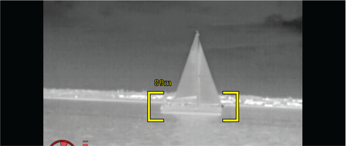
Augmented Reality
The Augmented Reality feature places layers of digital information directly over the top of the Video app’s video feed. Data from the Chart app is used to generate informative text and images (flags) on the Video app. When calibrated correctly, ClearCruise ™ Augmented Reality accurately overlays automatically-updating flags on the Video app so they overlap real-life objects.
Required components for Augmented Reality (IP cameras)
- MFD (Axiom, Axiom Pro or Axiom XL)
- AR200 Augmented Reality Sensor
- IP camera (CAM210IP or CAM220IP)
- LightHouse ™ software (v3.7 or later)
Required components for Augmented Reality (M-Series cameras)
- MFD (Axiom, Axiom Pro or Axiom XL)
- AR200 Augmented Reality Sensor
- M-Series camera (M100, M200 and M300 Series)
- M100 / M200-Series cameras require LightHouse ™ software version 3.9 or later.
- M300-Series cameras require LightHouse ™ software version 3.10.71 or later.
|
Important:
Cameras utilizing ClearCruise ™ Augmented Reality are subject to an unstable image on rough waters. |
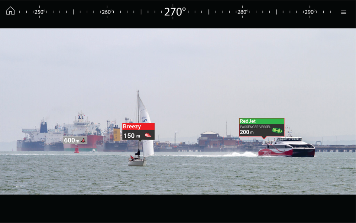
| Note: ClearCruise’s performance is dependent on environmental conditions and is not a replacement for maintaining a visual watch. |
Camera setup
Refer to your camera’s installation manual to determine the correct physical installation and connections for using the camera as part of an Augmented Reality system.
A number of additional camera-related settings and calibrations must be completed in the Video app before Augmented Reality features can be used:
- Camera height above the waterline.
- Camera direction.
- Camera horizontal field of view [not required for cameras which auto assign their field of view].
- Horizon calibration.
Note:
|
Fixed camera calibration
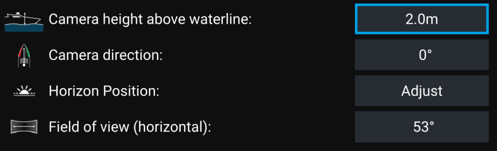
|
Note:
Incorrect physical camera installation and incorrect settings provided in the camera setup page could result in an inaccurate Augmented Reality overlay. |
- To adjust the values of Camera height above waterline, Camera direction and Field of view, select the value boxes of each option and adjust using the arrows.
|
Menu item |
Options |
|---|---|
|
Camera height above waterline |
|
|
Camera direction |
|
|
Field of view |
|
- To Calibrate horizon, use the up, down, rotate left and rotate right arrow keys until the red line is placed on the horizon. When the line is in position, select Save.
|
Important:
Calibrating the horizon correctly is essential for accurate Augmented Reality overlay. Calibrating on calm water and in clear sight of the horizon is recommended. |
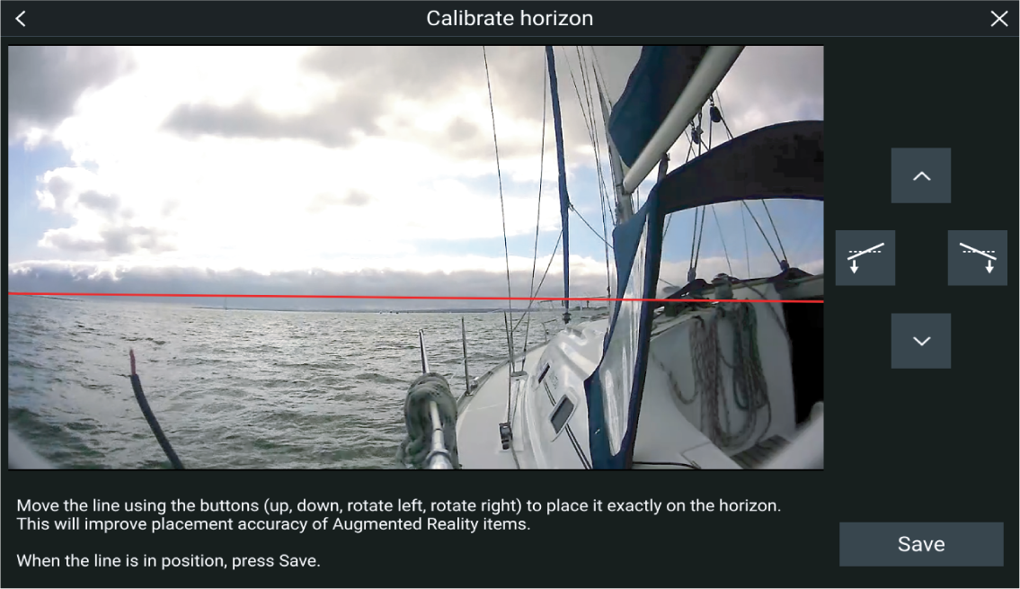
Pan and Tilt camera calibration
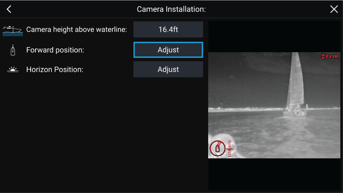
|
Note:
Incorrect physical camera installation and incorrect settings provided in the camera setup page could result in an inaccurate Augmented Reality overlay. |
- To adjust the values of Camera height above waterline select the value box and adjust using the arrows.
|
Menu item |
Options |
|---|---|
|
Camera height above waterline |
|
- To Calibrate the camera’s Forward Position adjust the camera direction so the vertical black line is positioned directly forward, parallel to your vessels forward position.
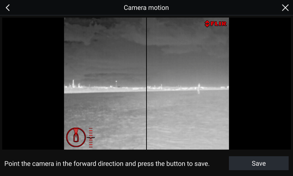
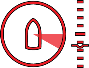
- To Calibrate the camera’s Horizon position use the arrow keys to align the horizontal red line so it is level with the horizon.
- Pan and tilt the camera 360° during calibration to ensure the horizon line has been positioned correctly.
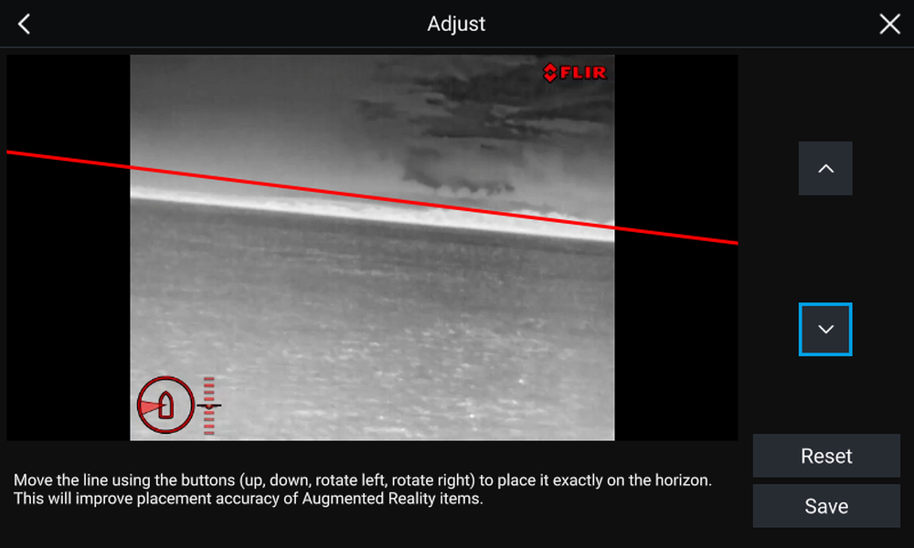
|
Important:
Calibrating the horizon correctly is essential for accurate Augmented Reality overlay. Calibrating on calm water and in clear sight of the horizon is recommended. |
AR200 setup for Augmented Reality
ClearCruise ™ object detection overview
Objects that visually differ from the water will be identified by the camera as a “non-water” object.
The following features are available with Object detection:
- Highlight detected objects — Enables/disables object highlighting, which automatically identifies and highlights “non-water” objects.
- Beep on detection — Enables/disables a beep when an object is detected (Highlight detected objects must be enabled)
- Display estimated range — Enables/disables display of an object’s estimated range from your vessel (Highlight detected objects must be enabled, and object must be closer than approximately 100 m (~300 ft)).
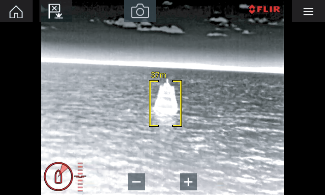
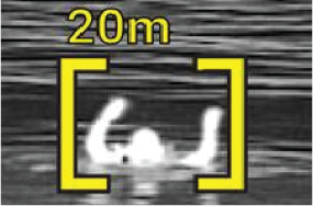
ClearCruise settings (Object Detection)
Video app > Settings > ClearCruise
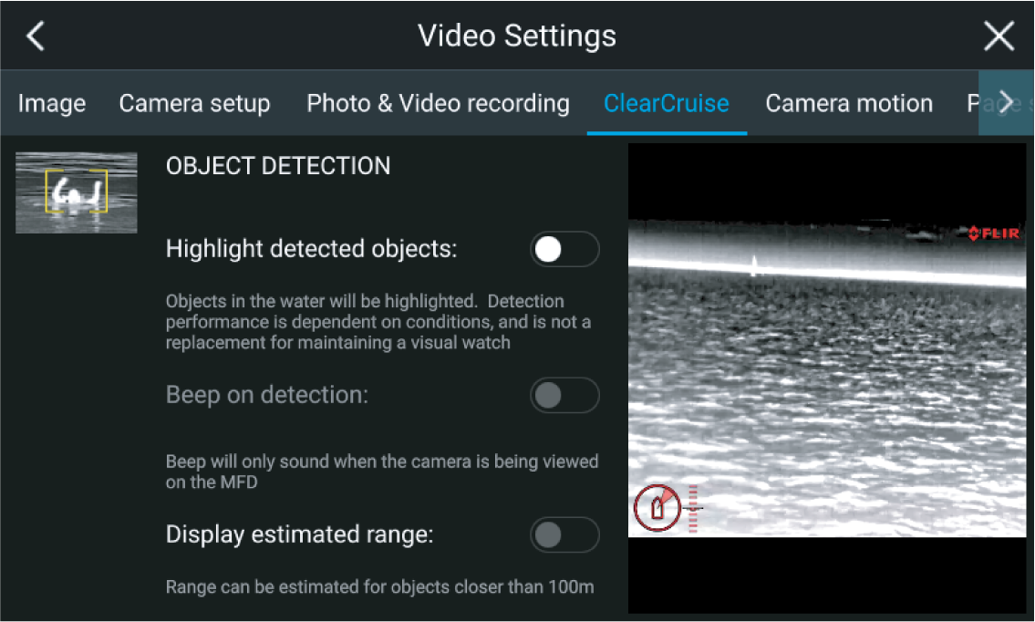
|
Setting |
Description |
|---|---|
|
Highlight detected objects |
Enables/disables object highlighting. |
|
Beep on detection |
Enables/disables an audible beep when an object is detected (Highlight detected objects must be enabled). |
|
Display estimated range |
Enables/disables display of an object’s estimated range from your vessel (Highlight detected objects must be enabled, and the object must be closer than approximately 100 m (~300 ft). |
| Important: ClearCruise Object Detection is only compatible with cameras that are positioned upright. ClearCruise Object Detection will not function with cameras that are upside down and have vertical flip enabled. |
Augmented Reality (AR) overview
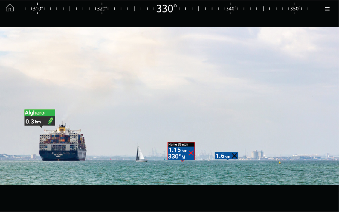
The Augmented Reality feature places layers of digital information directly over the top of the Video app’s video feed. Data from the Chart app is used to generate informative text and images (flags) on the Video app. When calibrated correctly, ClearCruise ™ Augmented Reality accurately overlays automatically-updating flags on the Video app so they overlap real-life objects.
The Augmented Reality feature requires an Axiom, Axiom Pro or Axiom XL MFD, an AR200 sensor and a compatible camera.
For more information, refer to: ClearCruise ™ features
Note:
|
| Important: Rear-facing cameras with a flipped or mirrored image may not place Augmented Reality content as accurately as a forward-facing camera. |
Augmented Reality flags
All flags display an icon and your vessel’s distance from the target’s location.
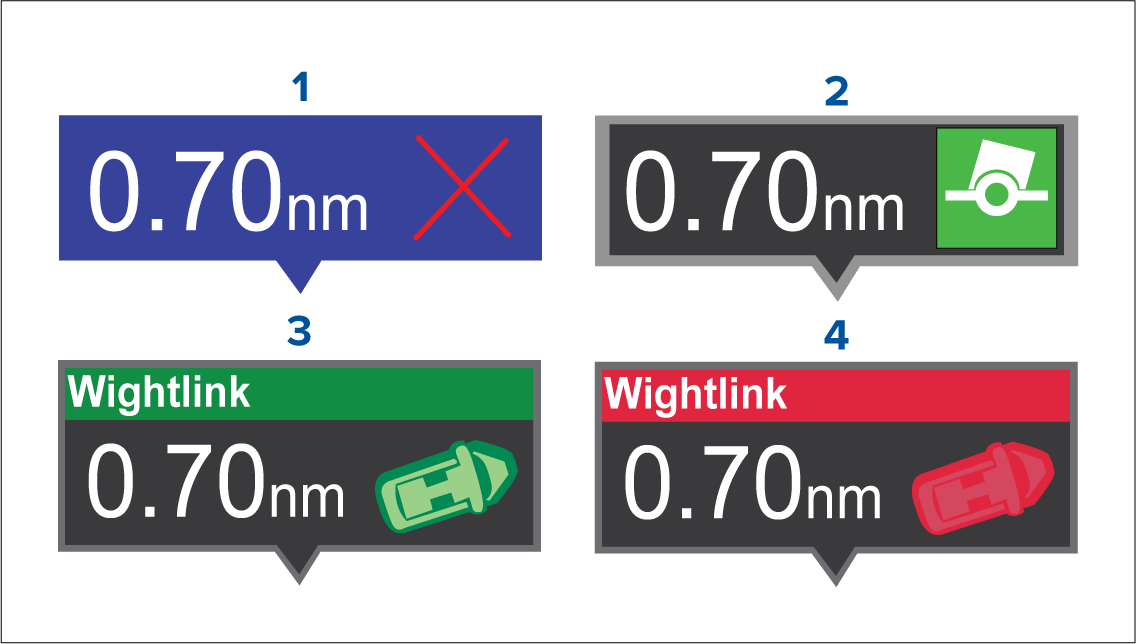
|
1 |
Waypoint flag |
|
2 |
Chart Object flag (buoy) |
|
3 |
AIS Target flag (passenger ferry; icon points in the direction of travel relative to the camera feed) |
|
4 |
Dangerous AIS Target flag (passenger ferry; icon points in the direction of travel, relative to the camera feed) |
| Note: AIS flags update periodically; however, accurate placement is not guaranteed. |
- AIS Targets, Waypoints and Chart Object flags can be quickly enabled / disabled via buttons in the Video app.
- The maximum range within which flags are automatically shown can also be adjusted in the Video app.
- For more information on adjusting flag settings, refer to: ClearCruise ™ features
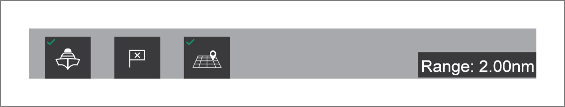
Selected flags
A flag is an onscreen visual overlay element displayed in the Video app when the Augmented Reality features are enabled. A flag represents an object from the Chart application: e.g. AIS target, Waypoint, or other chart object.
When a flag is selected, the corresponding object is also highlighted in the Chart app. Conversely, selecting an object in the Chart app highlights the corresponding flag in the Video app.
Only one flag may be selected at a time.
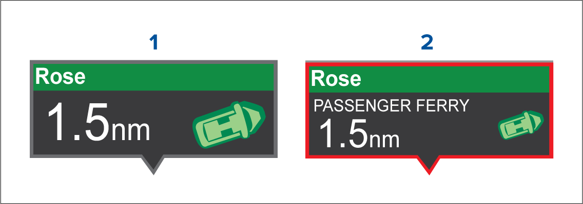
|
1 |
AIS Flag |
|
2 |
Selected AIS Flag |
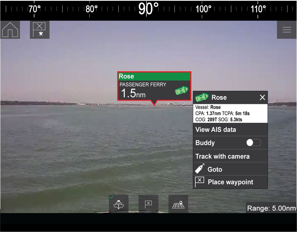
Selecting a flag highlights it in red and provides additional information about the object in a context menu. The menu also provides additional features. The range of features available in the context menu depends on the type of object selected:
AIS Target Flag
|
Option |
Description |
|---|---|
|
AIS Target name |
The name of the target vessel. |
|
Target data |
Vessel (name), CPA, TCPA, COG, SOG. |
|
View AIS data |
Displays the AIS data transmitted by the target vessel. |
|
Buddy (toggle ON/OFF) |
Add the vessel to your “Buddy List”, with the option to rename it. The Buddy feature enables you to add AIS-equipped friends and regular contacts to a “Buddy List” on your MFD. As soon as a vessel on your Buddy List comes within range of your AIS receiver, the onscreen vessel icon changes to indicate this. |
|
Goto |
The Chart app will plot a direct route to the last known location of the target. |
|
Place waypoint |
The Chart app will place a waypoint at the last known location of the target. |
Waypoint Flag
|
Option |
Description |
|---|---|
|
Waypoint name |
The name of the waypoint. |
|
Target data |
Lat, Lon, Rng, Brg. |
|
Goto |
The Chart app will plot a direct route to the last known location of the target. |
|
Delete |
Delete the waypoint. |
|
Edit |
Edit the waypoint’s Name, Symbol, Group, Position, and add a Comment. |
Chart Object Flag
|
Option |
Description |
|---|---|
|
Chart Object name |
The name of the chart object. |
|
Target data |
Lat, Lon, Rng, Brg. |
|
Goto |
The Chart app will plot a direct route to the last known location of the target. |
Goto flag
A Goto flag will appear in the last known location of the selected flag in both the Video and Chart apps, and in the Video app’s Compass bar. The flag is displayed with a Goto icon, as a blue copy of the original flag.
Selecting the Goto flag makes it a selected flag, and also displays a context menu providing more information about the location of the flag, and the option to stop a goto action.
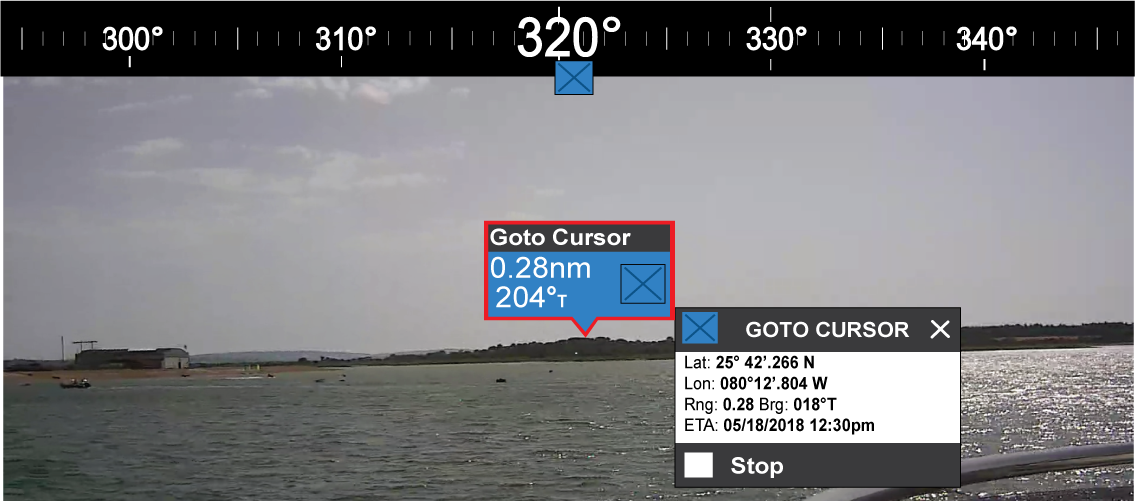
- Selecting Stop removes the Goto flag from the Video app and Chart app.
- If the camera loses sight of the Goto flag, it will display red and green navigational arrows on the Compass bar, indicating whether you need to turn port or starboard to regain sight of the flag. However, this only works if the camera is forward-facing.
ClearCruise settings (Augmented Reality)
|
Setting |
Description |
|---|---|
|
AIS labels |
Enables/disables the display of other vessels as Augmented Reality flags (requires AIS). |
|
Hide static targets |
Enables/disables the display of AIS targets travelling under 2 knots (requires AIS). |
|
Waypoints |
Enables/disables the display of Waypoint Augmented Reality flags. |
|
Chart objects |
Enables/disables the display of Chart objects (requires compatible charts). |
|
Cartography source |
Select the cartography source that the ClearCruise ™ features will use for the display of chart objects in the Video app Augmented Reality features. (Requires compatible charts). |
|
Compass |
Enables/disables the display of the Compass bar in the Video app. |
|
Range limit |
Sets the maximum range at which the camera will detect and display Augmented Reality flags. This range is displayed visually in the Chart app with the “FOV cone”. Refer to: Field of View . For the maximum range supported by your camera, refer to: Range limit |
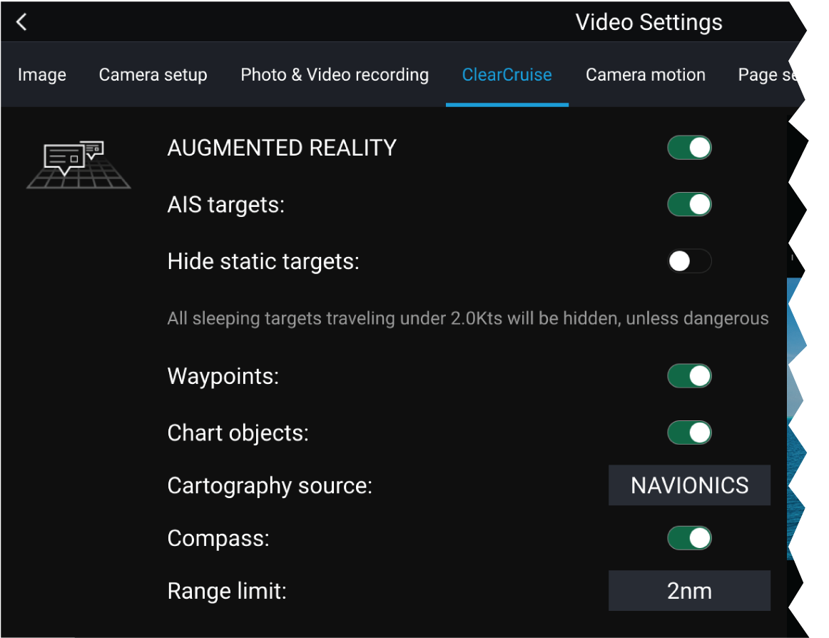
|
Note:
The variety of chart objects is dependent on the selected cartography source. For more information on different cartography sources, refer to: Find nearest |
Range limit
The range limit can be checked using the Field of View (FOV) cone in the Chart app. All AIS targets, Waypoints and Chart Objects within the area of coverage of the FOV cone can be displayed as Augmented Reality flags in the Video app. For more information, refer to: Field of View
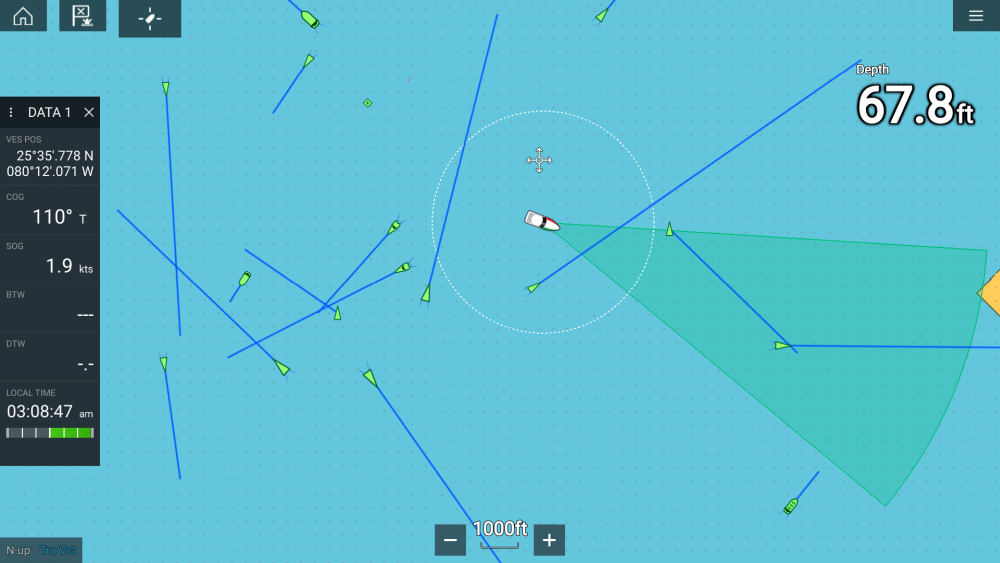
|
Note:
Some chart objects just outside of the FOV cone might still display in the Video app as flags. |
You can specify this range limit manually in the Video app: . Any adjustments you make will be reflected in the FOV cone display in the Chart app.
Roll correction
| Note: Roll correction is only available with IP cameras. |
Roll Correction can be enabled/disabled in the Video app: .
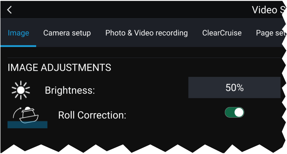
When enabled, the Roll Correction feature accounts for the boat tilting and stabilizes the video feed accordingly. This means that the video feed’s horizon will be parallel with the actual horizon. When disabled, the video feed will tilt with the boat and the MFD screen.
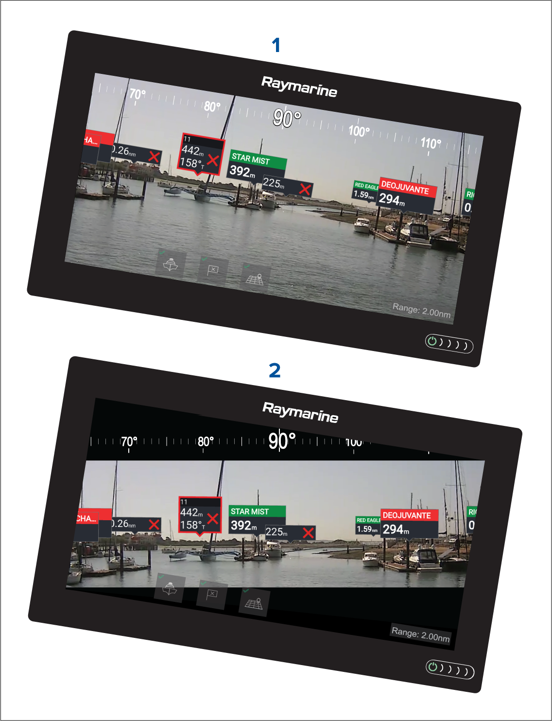
| 1 | Roll correction disabled |
| 2 | Roll correction enabled |
AR200 Calibration (Linearization)
Calibration is achieved using an automatic linearization process. The linearization process starts automatically after your vessel has turned approximately 100°, when travelling at a speed of between 3 to 15 knots. The linearization process requires no user input, however at least a 270° turn is required before linearization can be completed. The duration of the linearization process can be decreased by completing a full 360° turn, when travelling at a speed of between 3 to 15 knots. The linearization process can also be restarted at anytime.
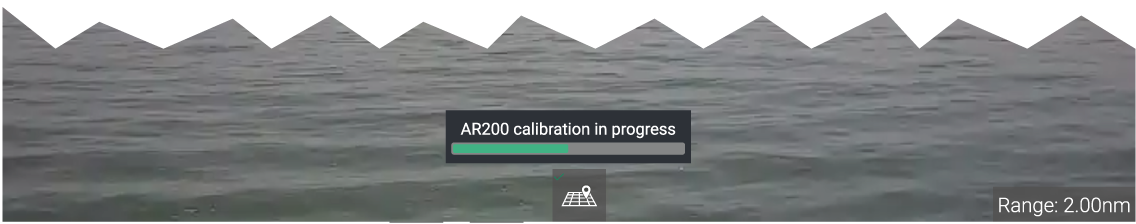
In the Video app the Linearization progress bar is displayed when linearization is in progress. The bar is filled to indicate completeness, and will turn Red if the process is paused or otherwise interrupted.
The time taken to complete the linearization process will vary according to the characteristics of the vessel, the AR200’s installation location, and the levels of magnetic interference present at the time linearization is performed.
Magnetic interference can be caused by objects onboard your vessel, such as:
- Speakers
- Electronic equipment
- Electrical cabling
- Metal bulkhead or hull
Magnetic interference can also be caused by external objects in close proximately to your vessel, such as:
- Metal hulled vessels
- Underwater electrical cables
- Marine pontoons
Magnetic deviation
The automatic linearization process results in a deviation value being set for your AR200. If Augmented Reality flags in the Video app are not aligned with their onscreen objects, or the compass is out of alignment, you should check the AR200’s current calibration settings. For instructions on how to do this, refer to: AR200 calibration settings
AR200 calibration settings
The AR200 calibration page can be accessed using your Data master MFD; from the Homescreen select: .
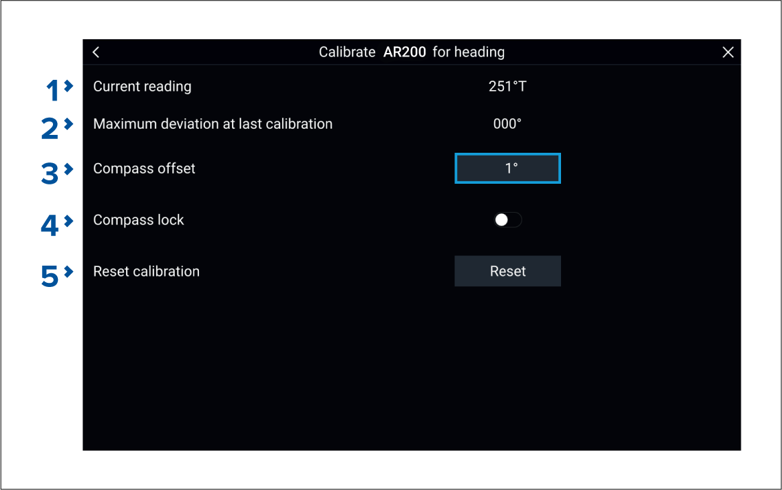
|
1 |
The current heading reported by the AR200. |
|
|
2 |
Maximum deviation at last calibration: The maximum deviation reported during the last linearization process.
Calibration in progress: While linearization is in progress the progress percentage is displayed. |
|
|
3 |
Once the linearization process has completed, it is possible that the heading value may be slightly out of alignment. This is common where installation space is limited and the AR200 is not properly aligned with your vessel’s longitudinal axis. In this case, it is possible to manually adjust the Compass offset. |
|
|
4 |
When enabled, the Compass lock prevents the continual monitoring and adaptation of the compass linearization process. For more information, refer to: Compass lock . |
|
|
5 |
You can reset your AR200’s current linearization settings by selecting Reset calibration |
Continual monitoring and adaptation
To ensure optimum performance, after the initial linearization process is complete the unit continues to monitor and adapt the compass linearization to suit current conditions.
If the conditions for linearization are less than ideal, the automatic linearization process temporarily pauses until conditions improve again. The following conditions can cause the linearization process to temporarily pause:
- significant magnetic interference is present
- vessel speed too slow or too fast
- rate-of-turn too slow or too fast
Compass lock
This feature is particularly useful for vessels in environments that are exposed to strong magnetic disturbances on a regular basis (such as offshore wind farms or very busy rivers, for example). In these situations it may be desirable to use the Compass lock feature to disable the continuous linearization process, as the magnetic interference may build a heading error over time.
| Note: The compass lock may be released at any time, to allow the compass continual monitoring and adaptation to re-commence. This is particularly useful if planning a long voyage. The earth’s magnetic field will change significantly from one geographical location to another, and the compass can continually compensate for the changes, ensuring you maintain accurate heading data throughout the voyage. |
Audio app
Audio app overview
The Audio app can be displayed in Fullscreen and half screen portrait app pages.
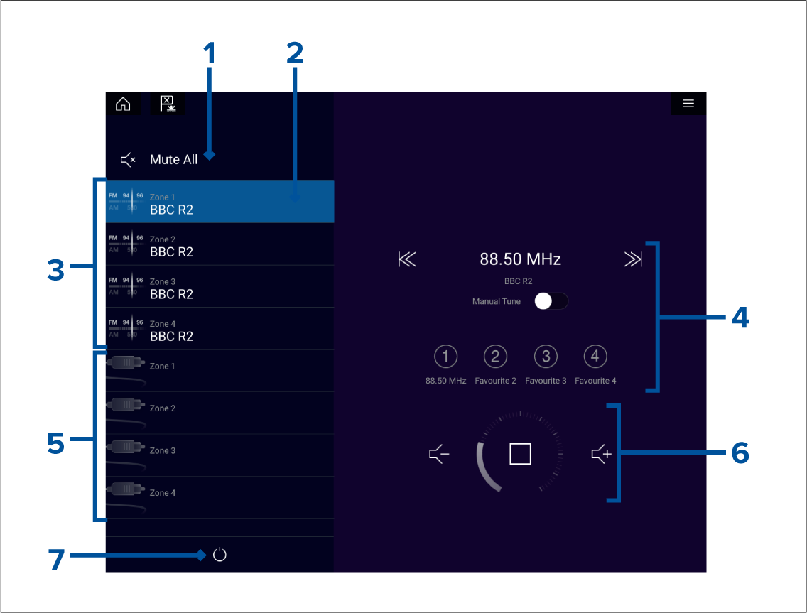
- Mute All — Mutes all zones on the currently selected system.
- Currently selected zone.
- System 1 available zones.
- Audio source and controls for currently selected zone.
- System 2 available zones.
- Zone volume and player controls for currently selected zone.
- Power — Power on or off connected entertainment systems.
Compatible entertainment systems
SiriusXM receivers
|
Model number |
Raymarine part number |
Supported Network connection |
|---|---|---|
|
SR150 |
E70161 |
Ethernet / RayNet |
|
SR200 |
E70499 |
Ethernet / RayNet |
Rockford Fosgate entertainment systems
|
Model number |
Raymarine part number |
Supported Network connection |
|---|---|---|
|
RMX-2 |
E70397 |
NMEA 2000 |
|
RMX8DH |
E70394 |
NMEA 2000 |
|
RMX8BB |
E70395 |
NMEA 2000 |
|
RMX5CAN |
E70396 |
NMEA 2000 |
Fusion entertainment systems
|
Model number |
Supported Network connection |
|---|---|
|
AV750 |
NMEA 2000 Ethernet |
|
AV755 |
NMEA 2000 Ethernet |
|
BB100 |
NMEA 2000 |
|
BB300 |
NMEA 2000 |
|
RA70 |
NMEA 2000 |
|
RA70N |
NMEA 2000 |
|
RA205 |
NMEA 2000 |
|
RA670 |
NMEA 2000 Ethernet |
|
RA770 |
NMEA 2000 Ethernet |
|
SRX400 |
Ethernet |
|
UD750 |
NMEA 2000 Ethernet |
|
UD755 |
NMEA 2000 Ethernet |
Audio app controls
Audio player controls
| Icon | Description | Function | |
|---|---|---|---|
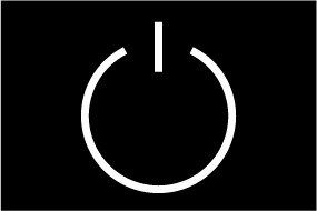
|
Power Off |
Powers off the Entertainment system. |
|
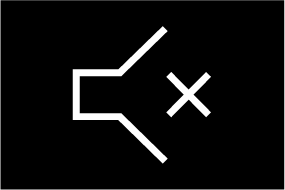
|
Mute All |
Mutes all audio zones. |
|
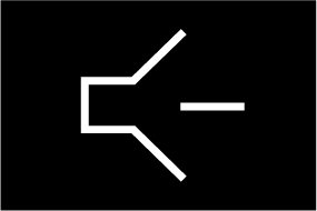
|
Volume Down |
Decreases volume for current zone. |
|
|
Volume Up |
Increases volume for current zone. |
|

|
Forwards |
|
|

|
Backwards |
|
|

|
Manual Tune |
|
|

|
Tune Up |
Manually searches up for radio stations/channels.
|
|

|
Tune Down |
Manually searches down for radio stations/channels.
|
|
|
Repeat |
|
|

|
Shuffle |
|
|

|
Play |
Select to commence playback. |
|

|
Pause |
Select to Pause playback. |
|

|
Stop |
Select to Stop (Mute) Radio devices. |
|

|
Like |
Like a track (Pandora only). |
|

|
Dislike |
Dislike a track (Pandora only). |
|

|
Radio presets |
Save your favorite radio stations/channels to 4 preset buttons. Press and hold to save, press once to change to saved station/channel.
|
Standard app controls
| Icon | Description | Function |
|---|---|---|
|
|
Menu icon |
Opens the app menu. |
|
|
Home icon |
Takes you to the Homescreen. |
|
|
Waypoint / MOB |
Place waypoint / activate Man overboard (MOB) alarm. |
|
|
Pilot icon |
Opens and closes the Pilot Sidebar |
Audio sidebar
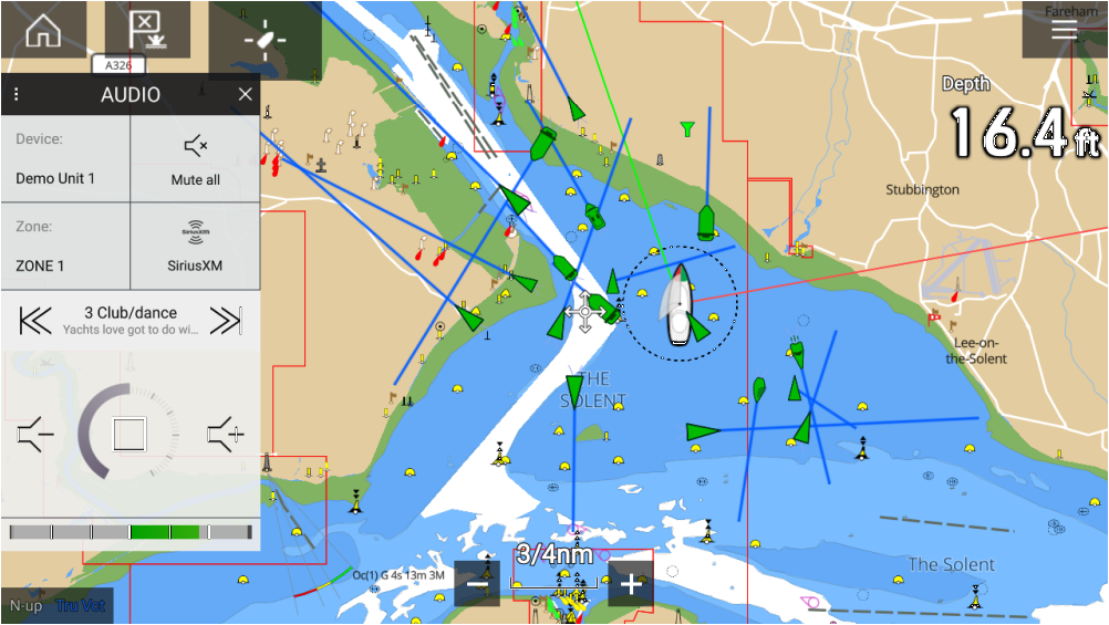
Opening the Audio app
Pre-requisites:
- Ensure your Entertainment system(s) are compatible by checking the latest details available on the Raymarine website. If in doubt please contact an authorized Raymarine dealer for advice.
- Ensure you have installed your Entertainment system(s) in accordance with the documentation that was supplied with the system.
The Audio app will open in 1 of 3 states:
Audio app displayed
If your Entertainment system is powered up and operational then the player controls are displayed and can be used to control your system.
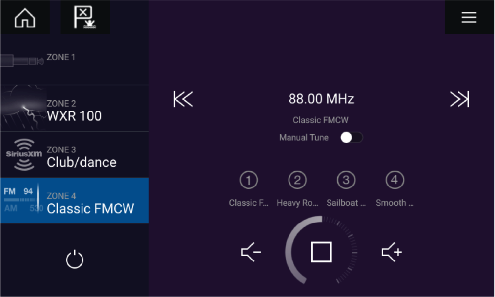
Entertainment system powered off
If all Entertainment systems are powered off then a Power icon is displayed for each connected system. An icon is also displayed to power on All systems. Selecting the Power icon will switch your Entertainment system on. Selecting the All icon will power on all connected systems.
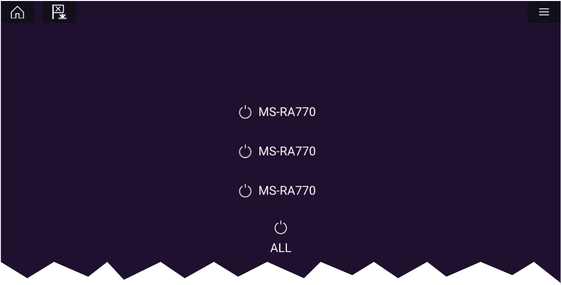
No audio devices found
If the Audio app is opened soon after powering on your MFD, the ‘No audio device found’ message may be displayed whilst the network is being established. If the message is displayed for more than 10 seconds, your MFD cannot connect to your Entertainment system(s). Ensure network and power connections to your Entertainment system(s) and MFD are correct and free from damage and then power cycle your system. If the Entertainment system(s) are still not displayed then refer to your equipment’s installation documentation for further troubleshooting information.
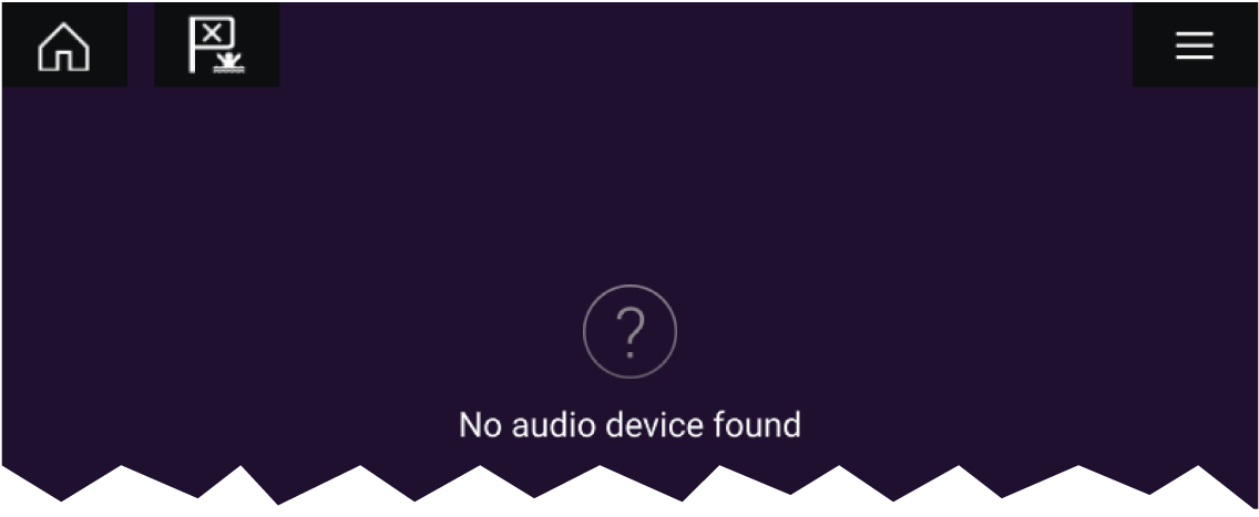
Getting started
Selecting an audio zone
Refer to the instructions provided with your entertainment system for details on naming your zones. This aids device and zone identification when multiple systems each with multiple zones are connected.
Selecting an audio source
The currently selected zone will switch to the selected audio source. Depending on your entertainment system all zones will change and play the same audio source, or you may be able to play a different source on each zone. Check the instructions provided with your system for details.
Muting and unmuting
Browsing for tracks
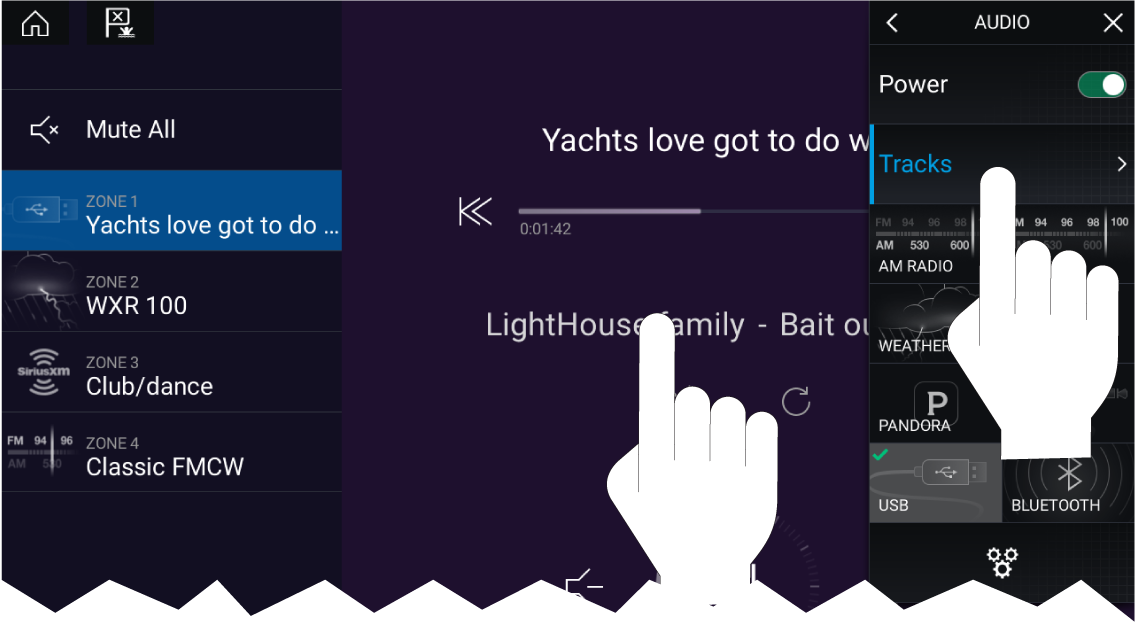
Browsing for stations / channels
| Note: For SiriusXM, channel control is not available from an external audio head unit. |
Saving presets
Powering off entertainment systems
Refer to the instructions provided with your entertainment system for details on naming your device. This aids device identification when multiple systems are connected.
Audio app menu options
|
Menu item |
Description |
Options |
|
|---|---|---|---|
|
Tracks |
Enables you to browse for tracks on USB/Bluetooth devices connected to your Entertainment system |
|
|
|
Channels |
Provides a list of available SiriusXM channels
|
Channel list |
|
|
Stations |
Provides a list of available Pandora stations |
Station list |
|
|
Audio sources |
Enables you to select an audio source connected to your Entertainment system |
|
|
|
Power |
Enables you to Power your Entertainment system on and off |
|
|

|
Displays the Settings page |
|
Audio app settings menu

Audio settings tab
|
Menu item |
Description |
Options |
|
|---|---|---|---|
|
Balance |
Allows you to control the left / right speaker balance of your entertainment system speakers. |
|
|
|
Fade |
Allows you to control the front / back speaker fade of your entertainment system speakers.
|
|
|
|
Crossover (Low pass filter): |
Allows you to select the crossover frequency. The Low Pass Filter (LPF) will block all audio frequencies above the threshold you specify. Selecting APF (All Pass Filter) will allow all frequencies. |
|
|
|
Crossover (High pass filter): |
Allows you to select the crossover frequency. The High Pass Filter (HPF) will block all audio frequencies below the threshold you specify. Selecting APF (All Pass Filter) will allow all frequencies. |
|
|
|
Multi-zone volume control: |
Allows you to select independent audio zones that are controlled by multi-zone volume control.
|
|
|
|
Reset: |
Performs a factory reset and power cycle of the SR200.
|
|
|
|
Diagnostics mode: |
Displays the SR200’s diagnostic information.
|
|
Page settings tab
|
Settings |
Description |
|---|---|
|
Data Overlays |
Enables configuration of Data overlays |
|
Edit split ratio |
Enables you to customize the position of the partitions in splitscreen app pages. |
Adjusting balance and fade controls
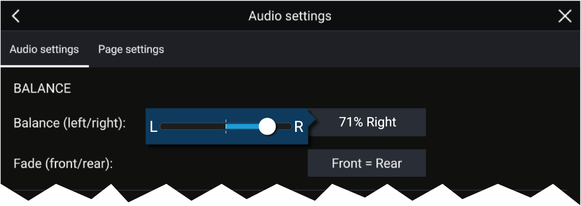
|
Note:
Fade controls are only available on Rockford Fosgate entertainment systems. |
Adjusting multi-zone controls
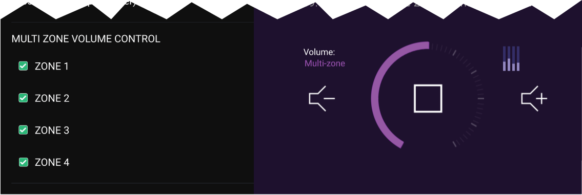
|
Note:
Multi-zone controls are only available on Fusion entertainment systems. |
SR200 diagnostics mode
- Reset — Performs a factory reset and power cycle of the SR200.
- Diagnostics mode — Displays the SR200’s diagnostic information.
PDF Viewer app
PDF Viewer app overview
A typical use for the PDF viewer is to display Raymarine product handbooks that you have downloaded from the Raymarine website (www.raymarine.com/manuals). PDF files must first be copied to a MicroSD card using an external device (such as a PC or tablet). You can then insert the MicroSD card into your MFD’s card slot, and access the PDF file(s) via the PDF Viewer app.
Note:
|
Opening PDF files
Select Browse to open a PDF file.
Recently-viewed files are displayed on the right-hand side of the initial app start screen, for quick access. These files can be opened, pinned to the top of the list, or removed from the list.
To access these options, long-hold touch on a filename to display the context menu.
Note:
|
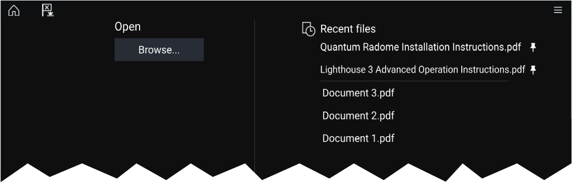
PDF Viewer controls
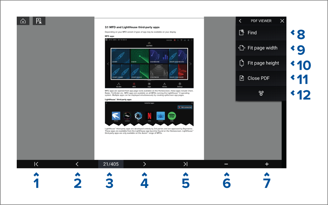
- First page — Select to display the first page of the PDF document.
- Page back — Select to display the previous page.
- Pages — Indicates current page and total number of pages. You can also tap this element and enter a specific page number.
- Page forward — Select to display the next page.
- Last page — Select to display the last page of the PDF document.
- Zoom out — Select to zoom out, in 10% increments.
- Zoom in — Select to zoom in, in 10% increments.
- Find — Select to display the onscreen keyboard and enter a search word or phrase.
- Fit page width — Zoom the document display to fit the width of the PDF page.
- Fit page height — Zoom the document display to fit the height of the PDF page.
- Close PDF — Closes the PDF and displays the initial PDF Viewer app start screen.
- Settings — Displays the Settings menu, which allows you to add data overlays to the PDF Viewer app.
Searching a PDF
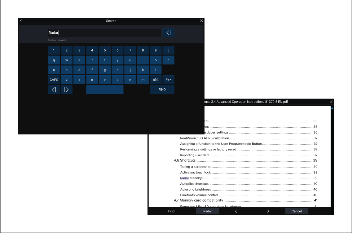
UAV (Unmanned Aerial Vehicle) app
|
|
Warning: UAV disclaimer |
|
The UAV app allows the FLIR multifunction display (“MFD”) to serve as an auxiliary controller for approved unmanned aerial vehicle (UAV) models. You are responsible for your own conduct while using the UAV and for any consequences thereof. You must use the UAV in accordance with all applicable legal regulations and safety recommendations of the UAV manufacturer. The primary controller should be readily accessible at all times while using the MFD as an auxiliary controller. FLIR accepts no liability for any damage, loss or injury caused by the UAV, whether caused by the use of the MFD or any other FLIR product. Particular attention must be paid to landing the UAV which must be done by the primary controller and not the MFD. By selecting continue, you confirm that you understand and accept these conditions. |
UAV app overview
UAVs and MFDs have a one-to-one relationship, meaning that you can only control a UAV from the MFD that it is physically connected to. On an MFD network, each MFD can be connected to a different UAV, if required.
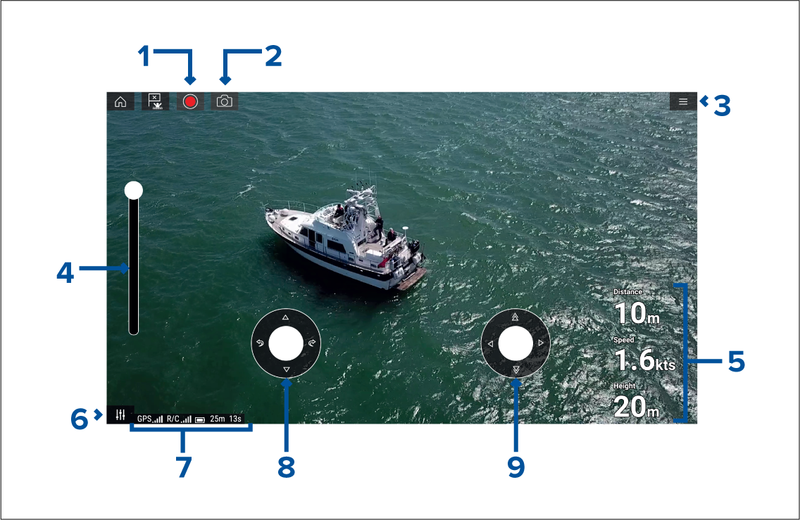
|
1 |
Record Start recording your UAV’s video feed to a memory card inserted into the UAV’s memory card slot. While recording, the Record icon is replaced with a Stop icon and a time counter is displayed. |
|
|
2 |
Take photo Take a screenshot of what is currently displayed in the UAV’s video feed. The image is saved to a memory card inserted into the UAV’s memory card slot. |
|
|
3 |
Menu Opens the UAV app menu. |
|
|
4 |
Gimbal pitch control Adjusts the pitch of the UAV’s camera gimbal, from pointing forwards (control at top of slider) to pointing straight down (control at bottom of slider). |
|
|
5 |
Flight data Distance, Speed and Height data is displayed onscreen.
|
|
|
6 |
Controls Provides access to the onscreen virtual joystick controls. |
|
|
7 |
Status area The status area provides the:
|
|
|
8 |
Virtual joystick Provides Up, Down, Turn left and Turn right controls. |
|
|
9 |
Virtual joystick Provides Forward, Backward, Move left and Move right controls. |
Note:
|
Compatible UAVs
UAV sport mode
UAV app settings menu
Advanced
| Settings | Description |
|---|---|
| Initial height after take-off: |
Specifies the height at which the UAV will hover once it has taken off. |
| Minimum safe height during UAV goto: |
Specifies the minimum safe height of the UAV when performing a Goto. |
| Action if remote control signal is lost: |
If your UAV loses connection to the remote controller then you can select whether your UAV Hovers in its current location or performs a Return to boat. |
| Minimum height: |
Specifies the minimum height of the UAV when performing a Return to boat. |
| Return distance: |
Specifies the distance from your vessel the UAV will reach when performing a Return to boat. |
| Height: |
Specifies the initial height of the UAV when performing a Fish on / Circle me. |
| Distance: |
Specifies the initial distance from your vessel when performing a Fish on / Circle me. |
Page settings
| Settings | Description |
|---|---|
| Data Overlays |
Enables configuration of Data overlays |
| Edit split ratio |
Enables you to customize the position of the partitions in splitscreen app pages. |
Data overlays in the UAV app are separate from the Flight data information.
UAV pre-requisites
Before you can use the MFD’s UAV app with your UAV you must have:
- set up your UAV in accordance with the instructions provided with the device.
- registered your UAV using the applicable DJI app (e.g.: DJI GO 4) on your mobile device.
- gained experience of launching, flying and retrieving your UAV.
- removed the RC cable from the side of your UAV’s remote controller.
- ensured the remote controller is not in Sport mode.
- Created a UAV app page icon on the MFD’s Homescreen.
Removing the RC cable
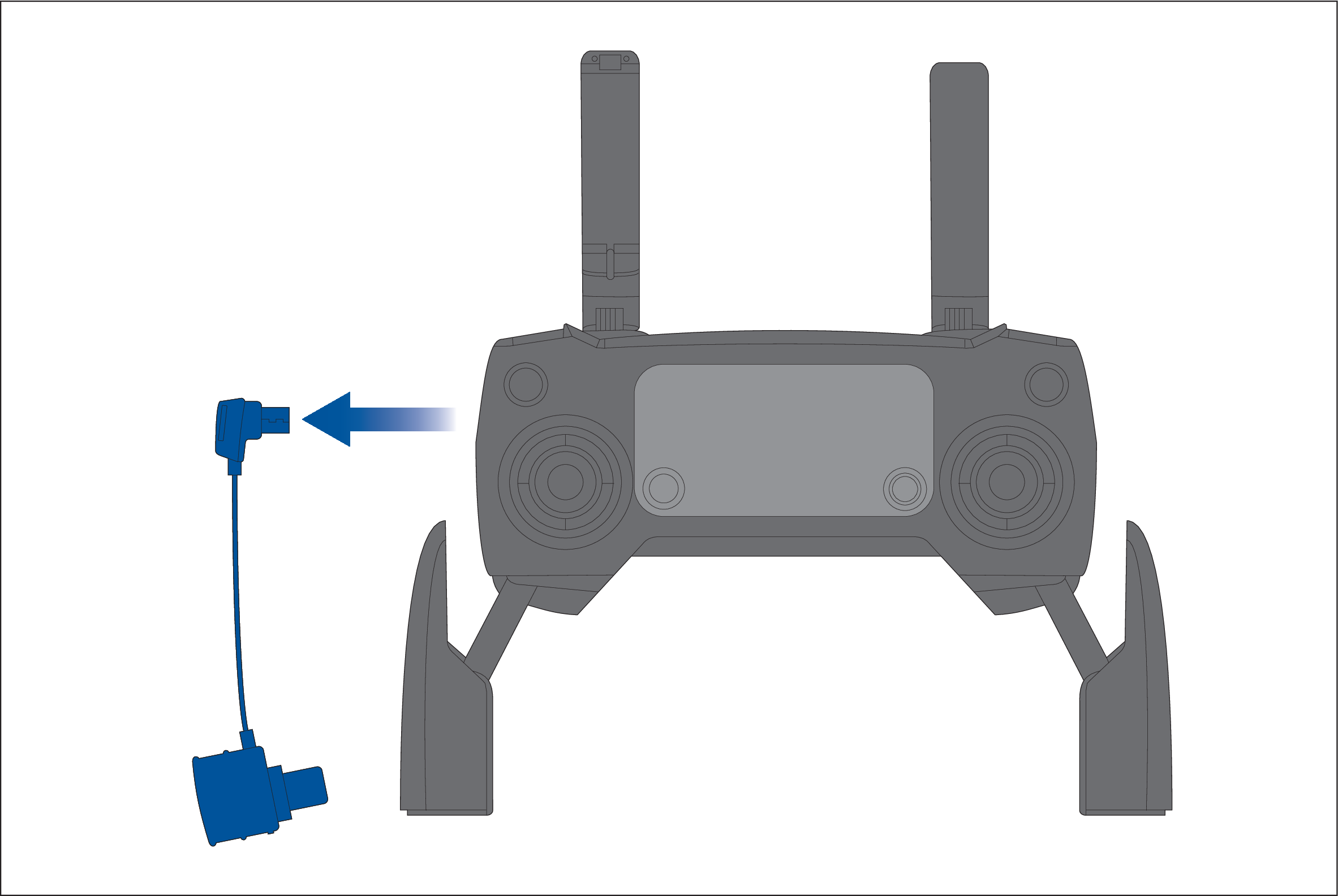
UAV controller connection
Note:
|
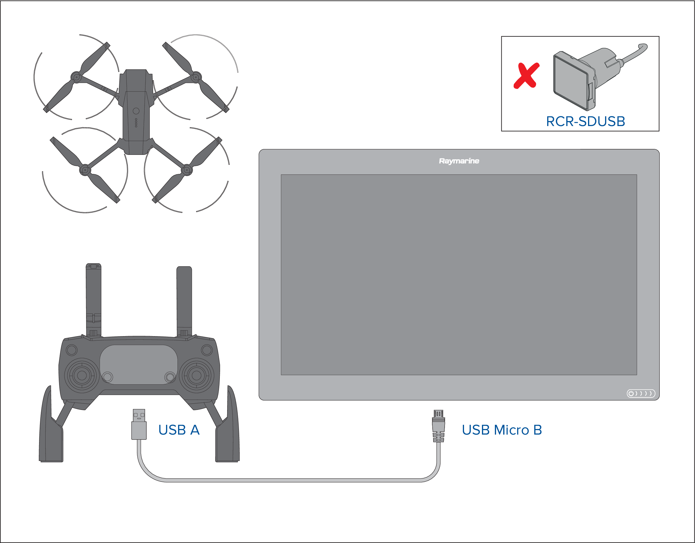
|
Important:
Ensure that the USB connection to your MFD is secure and protected against water ingress. |
UAV precautions
The following precautions should be followed:
- You will need to be an experienced, competent pilot as launching and retrieving the UAV on a vessel is more difficult due to confined space and vessel movement / drift.
- Only launch your UAV in calm wind and tide conditions. When attempting to launch or retrieve your UAV your vessel should be travelling at less than 1 knot and your captain should be ready at the helm to back down or maneuver the vessel to avoid accidental collisions
- Maintain awareness of your UAV’s battery status, remaining flight time, distance from your vessel and Wind and Tide conditions. A UAV flying against the wind will consume battery power more rapidly than when flying downwind or in calm conditions. Always budget sufficient power reserves to ensure the safe return and retrieval of your UAV.
- Maintain a permanent watch of your UAV while in flight. The UAV pilot or competent observer must maintain awareness of surrounding air and marine traffic while the UAV is in flight. The pilot must remain ready to take control of the UAV and manually fly it to avoid interfering with other vessels or aircraft.
- While your UAV’s controller is connected to your MFD it should be positioned so that it maintains line of sight with your airborne UAV. If the controller is not hand held then it must be secured to prevent it becoming disconnected from your MFD and to prevent unintentional button presses.
No-fly zones
It is illegal to fly your UAV in no-fly zones. No fly zones include:
- Airports
- Airfields
- Country borders
- Sensitive institutions
The Remote controller and the MFD will alert you that there is a no-fly zone. Your UAV will not enter the restricted airspace covered by a no-fly zone. You will also be unable to launch your UAV in restricted airspace. Please refer to the DJI app or the DJI website for more information on no-fly zones and their locations.
Getting started
UAV app page
UAV control features are integrated with the Chart app; when creating a UAV app page it is recommended that you create a splitscreen Chart / UAV app page.
Follow the instructions detailed in the Creating / Customizing an app page section for information on creating an app page. Chart / UAV splitscreen app pages will be set to a 30/70 page split by default.
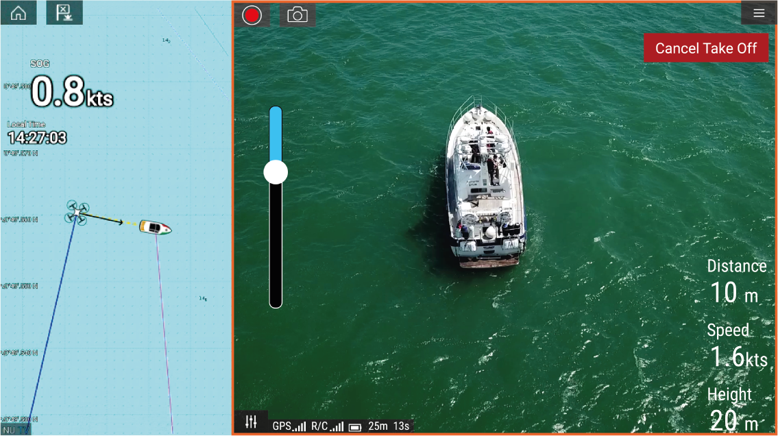
Opening the UAV app
The first time you open the UAV app and after each power cycle, a disclaimer is displayed. By selecting Continue you are agreeing to the terms of this disclaimer.
The UAV app will then open in 1 of 3 states:
No Wi-Fi connection
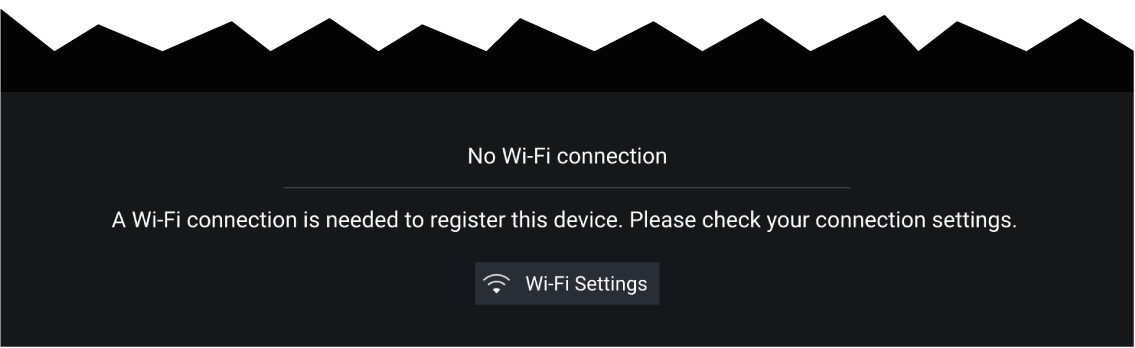
The first time you open the UAV app, after an MFD factory reset, or after you have updated your MFD’s software, the UAV app must be registered using an internet connection on your MFD. Select Wi-Fi Settings to create an internet connection.
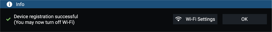
When registration is complete, if desired you can turn off your Wi-Fi connection by selecting Wi-Fi Settings and turning off your MFD’s Wi-Fi. Selecting OK will close the info box keeping your Wi-Fi connection turned on.
Registration failed
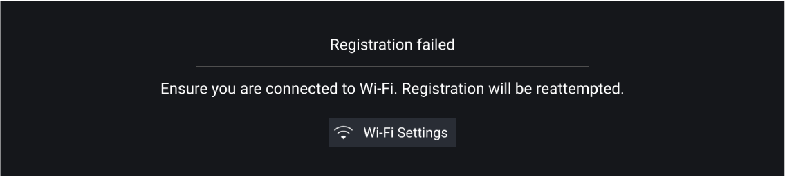
The registration failed notification is displayed if the DJI servers cannot be reached. Registration will be re-attempted automatically. If the failure persists, check your Wi-Fi and internet or try again later.
No connection detected
After successful registration, the ‘No connection detected’ notification is displayed. Connect the USB A end of your USB cable to the UAV’s primary controller. Once a successful connection is established, the notification will be closed.
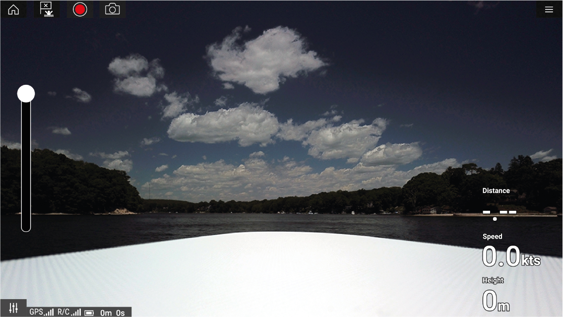
Launching the UAV
Controlling the UAV in flight
|
Note:
The Virtual joysticks take priority over your UAV’s remote controller’s joysticks, To use the remote controller’s joysticks hide the Virtual joysticks by selecting the Controls icon. |
Retrieving your UAV
|
Note:
The Return home manoeuvre can be cancelled at any time by selecting the Red, onscreen Cancel return to boat option. Once selected the UAV will stop and hover in its current position. |
Disconnect UAV remote controller from MFD
Fish on / Circle me mode
When your UAV is in Fish on / Circle me mode you should ensure your vessel speed does not exceed 10 knots or the UAV may not be able to keep up with your vessel. If your UAV cannot keep up slow your vessel speed.
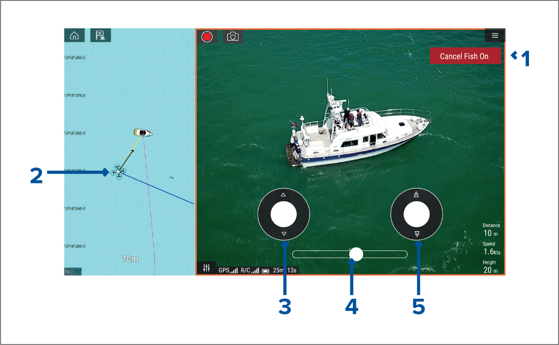
|
1 |
Cancel Fish On / Cancel Circle me Selecting Cancel Fish On / Cancel Circle me will stop Fish On / Circle me mode and the UAV will hover in its current location. If required you can manually stop recording by selecting the Stop icon. |
|
2 |
UAV icon The UAV icon can be displayed in the Chart app. The icon includes a camera heading graphic, a Course Over Ground (COG) vector and a line linking your vessel icon to your UAV icon. |
|
3 |
Virtual joystick In Fish On / Circle me mode the left virtual joystick provides Up and Down controls to adjust the UAV’s distance from your vessel. |
|
4 |
Rotation The Rotation slider control is used to adjust the UAV’s direction of rotation and rotation speed. With the control on the slider center line the UAV will maintain position in relation to your vessel. Moving the slider right of the slider center line rotates the UAV counter-clockwise and moving the slider control to the left of the center line rotates the UAV clockwise. The farther left or right the slider control is set the faster the rotation speed will be. |
|
5 |
Virtual joystick In Fish On / Circle me mode the right virtual joystick provides Forward and Backwards controls to adjust the UAV’s height from your vessel. |
|
Note:
During your initial MFD configuration the boating Activity you selected will determine whether the function is labelled Fish on or Circle me. If Fishing (freshwater), Fishing (saltwater) or Retail/demonstration is selected then the function is labelled Fish on, otherwise the function is labelled Circle me. |
UAV Chart integration
|
1 |
UAV COG The direction of the Blue line indicates the UAV’s current Course Over Ground (COG). The length of the line indicates the UAV’s predicted position when the specified vector Reference period has passed. The Vector Reference period can be adjusted from the vessel icon’s context menu. |
|
2 |
UAV Icon Displayed when the UAV option is enabled in the Chart app settings, and your UAV has a GNSS (GPS) position fix. |
|
3 |
Camera heading The Black Camera heading arrow is fixed to provide an indication of the direction the UAV’s camera is pointing towards. |
|
4 |
Line to vessel The Yellow dotted line represents the angle of the UAV’s position relative to your vessel. |
Showing or hiding the UAV icon
Performing a UAV Goto
You can stop a UAV Goto at anytime by selecting the Red Cancel UAV Goto that is displayed onscreen in the UAV app, when a UAV Goto is active. Cancelling a UAV Goto will stop the Goto action and the UAV will hover in its current location.
A UAV Goto can be cancelled at any time by selecting Stop UAV Goto from the Chart context menu.
UAV Emergency procedures
Controller signal to UAV lost
In the event that your UAV loses its connection to the primary controller, the UAV will perform 1 of 2 actions, depending on your selection in the Advanced setting menu: .
- Hover — The UAV will stop and hover in its current location. You should maneuver your vessel towards your UAV’s position and attempt to re-establish control. When control is re-established it is recommended that you retrieve the UAV and inspect it immediately.
-
Return to boat — The UAV will perform a Return to boat maneuver and hover at the Return distance and Minimum height specified in the Return to boat settings:
If connection between the Remote controller and UAV is not re-established, your UAV will attempt to land.
Low battery warnings
Ensure while flying your UAV that you remain aware of the remaining flight time and distance from your vessel at all times. You must return your UAV to your vessel and safely retrieve it before a low battery warning occurs. The UAV app will mirror the UAV’s primary controller battery state warnings.
- Normal low battery level warning — when the UAV reaches normal low battery level, in addition to the remote controller’s audible and visual warnings a warning is also displayed on your MFD. You should immediately return the UAV to your vessel and retrieve.
- Critical low battery warning — when the UAV reaches critical low battery level, your UAV will automatically perform a Return to boat maneuver and attempt to land. It is not recommended that you allow your UAV to reach critical low battery while in flight, as it could result in damage or loss of your UAV.
Assuming manual control
The UAV pilot has the ability to take manual control of the UAV at any time. Manual control may be required for normal in-flight maneuvering or positioning, or in emergency situations. The methods of assuming manual control are as follows:
- Virtual joysticks will need to be hidden, using the Controls icon before control is returned to the Remote controller.
- Enabling Sport mode on the UAV’s Remote controller at any time will override MFD controls. Fly with caution, as flight characteristics change in Sport mode.
- In an emergency, unplugging the USB cable from the Remote controller will override the MFD controls and immediately restore manual control to the Remote controller.
LightHouse third-party apps
LightHouse app launcher
| Important: The LightHouse app launcher and its associated third-party apps are not available on eS Series and gS Series MFDs. |
Select Apps from the Homescreen to open the app launcher page.
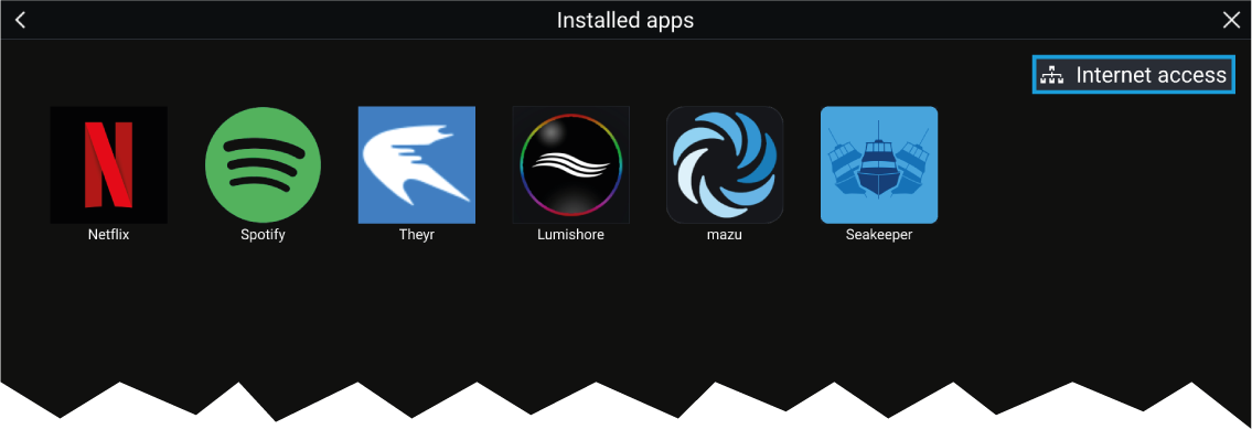
Selecting an app icon will launch the app. Selecting the Wi-Fi connection status button, located on the top right of the screen, will open the Wi-Fi connection settings to enable you to connect to the internet over Wi-Fi.
Apps may run in the background, enabling you to use your MFD as usual whilst, for instance, listening to music.
MFD alarms will be displayed and sounded as normal whilst using LightHouse third-party apps. When paired with a Bluetooth speaker, alarms will also be sounded through the speaker.
Bluetooth speaker volume can be controlled from the Shortcuts page or from the Status bar area on the Homescreen.
Note:
|
LightHouse third-party apps
LightHouse ™ third-party apps are apps that have been developed by third parties and approved for use on the LightHouse ™ 3 operating system.
|
Note:
Raymarine does not provide support for third-party apps or any related third-party hardware. Please refer to the relevant third party app developer for assistance and troubleshooting. Raymarine does not warrant that LightHouse ™ third-party apps are error-free, and will not be held liable for damages or injuries caused by improper or inappropriate use of these apps. |
|
|
Warning: Maintain a permanent watch |
|
Do NOT navigate whilst distracted by entertainment apps. Failure to maintain a permanent watch puts yourself, your vessel
and others at serious risk of harm.
|
Lighthouse third-party apps - Preloaded

|
|
|

|
|
|

|
|
|

|
|
|

|
|
|

|
|
|

|
|
|

|
|
|
|
|
|

|
|
|

|
|
|

|
Victron Energy
|
Lighthouse third-party apps - Downloadable
Note:
|

|
Buoyweather
|

|
PredictWind
|

|
Offshore
|
Installing Lighthouse third-party apps
| Note: Only APK-approved Lighthouse third-party apps can be installed on your MFD. APK-approved Lighthouse third-party apps can be downloaded from: http://www.raymarine.co.uk/lighthouse-apps/ |
| Note: You can uninstall Lighthouse third-party apps from your MFD by long pressing them and selecting uninstall. |
Internet connection
Connecting to the internet
Wi-Fi settings
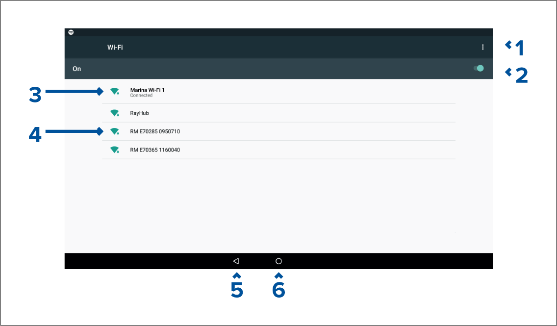
-
Wi-Fi options — Provides the following options:
- Add network — Manually add a network.
- Saved networks — View a list of all saved networks.
- Refresh — Rescan available networks.
- Advanced — View advanced network settings.
- Enable/Disable Wi-Fi.
- Connected access point.
- Available access points.
- Back button.
- Home button
Bluetooth speaker set up
Enabling and disabling Bluetooth
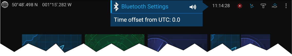
Bluetooth Settings
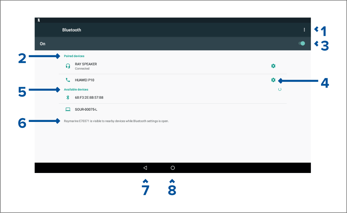
-
Bluetooth options — Provides the following options:
- Refresh — Selecting refreshes the list of available devices.
- Rename this device — Allows you to rename the Bluetooth name your MFD uses.
- Show file received — Not used as your MFD cannot receive files over Bluetooth.
- Paired devices — List of devices paired with your ~MFD.
- Enable/Disable Bluetooth.
- Paired device settings — Allows you to rename the paired device or forget the device.
- Available devices — List of available Bluetooth devices.
- MFD Bluetooth name.
- Back button.
- Home button.
Pairing a Bluetooth speaker
If pairing is successful the speaker will appear in the Paired devices list and display the Connected message.
Bluetooth volume control
Homescreen
From the Homescreen select the Status area and then select the Speaker symbol to display the Bluetooth volume control for LightHouse ™ app and MFD alarms.
Shortcuts page
Press or swipe the Power button to display the Shortcuts page and then select the speaker symbol to display the Bluetooth volume control for LightHouse ™ apps and MFD alarms.
Mobile app support
Raymarine mobile apps
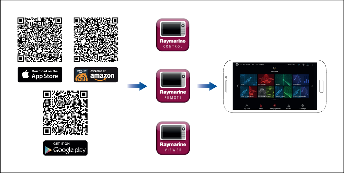
Connect to Wi-Fi - Android
Open your Android device’s Wi-Fi from the top drop down menu or via Settings.
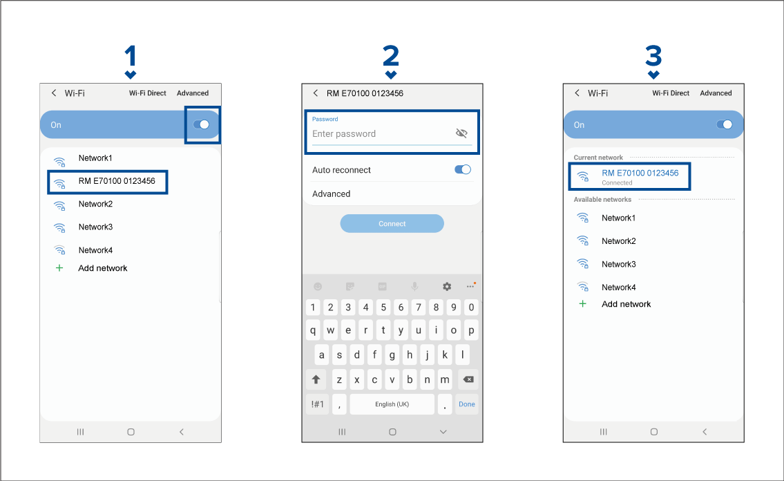
Connect to Wi-Fi - iOS
Open your iOS device’s Wi-Fi from the top drop down menu or via Settings.
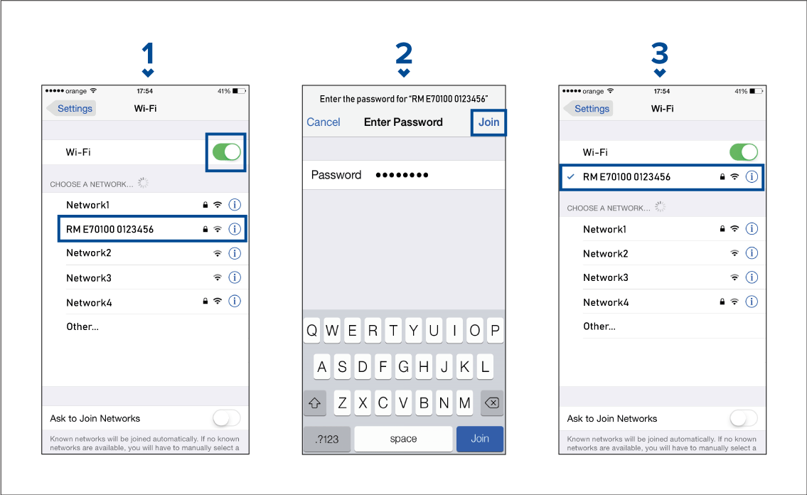
RayConnect
- Login with an existing Raymarine account or create one using the app.
- Purchase LightHouse Charts with the Chart Store.
- Define the regions and types of cartographic data you want the chart to contain.
- Download the chart data straight to an SD card in your Axiom MFD.
Content selection
- Undo — Remove the last defined area.
- Clear all — Remove all defined areas
Downloading a chart file for the first time
The following pre-requisites should be observed:
- If using mobile data, ensure you have sufficient data allowance remaining to prevent being charged.
- Ensure Allow devices to connect via Wi-Fi is enabled in your MFD settings: .
If you are saving charts to MicroSD card:
- It is recommended that the card is in the exFAT format.
- Ensure that the MicroSD card is inserted into the MFD’s card slot prior to commencing the process (this will create the necessary Lighthouse_ID file in the card’s root directory.
|
Important:
Once a storage location (e.g.: internal memory or SD card) has been chosen for your chart you cannot change it. |
- For MicroSD cards the Lighthouse ID files is located in the root directory (e.g.: SD card 1\Lighthouse_ID.txt).
- For internal MFD storage, the Lighthouse ID file is located in the Cartography folder (i.e.: Internal\Cartography\Lighthouse_ID.txt)
|
Note:
For information on connecting your mobile device, refer to:
|
|
Note:
When updates to your charts are available you will be able to download these from the My Charts tab. |
Account settings
You can edit your Raymarine account details using the Account menu.
You can edit the account’s:
- Name
- Email address
- Password
- Region
- News and offers notification settings
Fishidy sync
|
Note:
Fishidy sync requires:
|
|
Note:
Fishidy is currently available in:
|
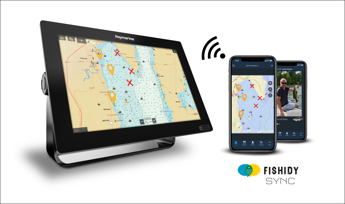
Enable sync
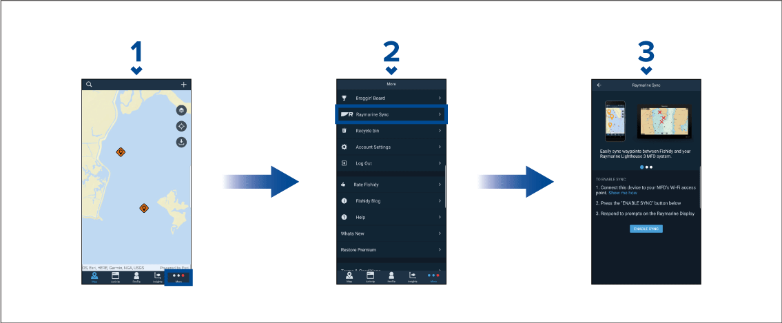
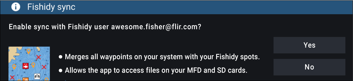
Once enabled, data will automatically sync in real-time across both devices via Wi-Fi.
Note:
|
Disable sync
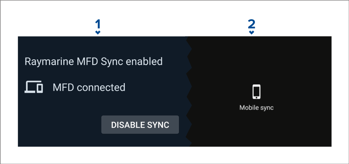
Controlling your MFD using RayControl
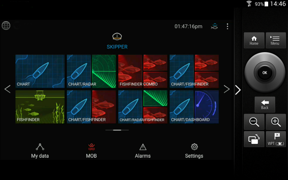
Controlling your MFD using RayRemote
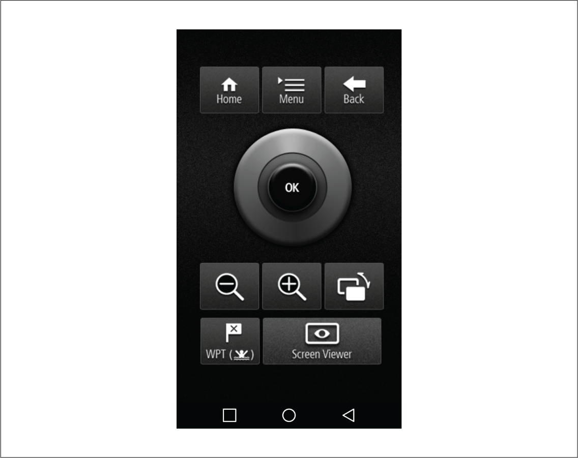
Viewing your MFD screen using RayView
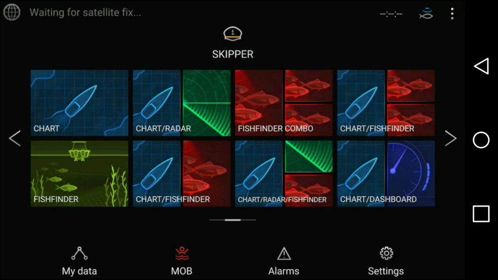
Troubleshooting
Troubleshooting
The troubleshooting information provides possible causes and corrective action required for common problems associated with installation and operation of your product.
Before packing and shipping, all Raymarine products are subjected to comprehensive testing and quality assurance programs. If you do experience problems with your product this section will help you to diagnose and correct problems in order to restore normal operation.
If after referring to this section you are still having problems with your product, please refer to the Technical support section of this manual for useful links and Raymarine Product Support contact details.
Diagnostic product information
To view diagnostic product information, select View all product info from the Diagnostics pop over menu: .
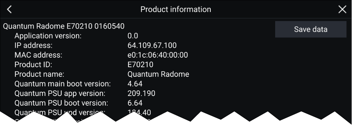
Saving product information
A .json file will be saved, using your chosen filename to your memory card.
You may view the file using a most standard notepad applications.
Power up troubleshooting
Product does not turn on or keeps turning off
| Possible causes | Possible solutions |
|---|---|
|
Blown fuse / tripped breaker. |
|
|
Poor / damaged / insecure power supply cable / connections |
|
|
Incorrect power connection |
The power supply may be wired incorrectly, ensure the installation instructions have been followed. |
Product will not start up (restart loop)
| Possible causes | Possible solutions |
|---|---|
|
Power supply and connection |
See possible solutions from the table above, entitled ‘Product does not turn on or keeps turning off’. |
|
Software corruption |
|
|
|
Warning: Factory reset warning |
|
Performing a factory reset will restore all system and app settings to factory defaults and erase all user data (such as waypoints,
routes, tracks, camera recordings and photos).
|
Performing a power on reset — Axiom ™
Important:
|
Performing a power on reset - Axiom Pro
|
Important:
Before performing a power on reset ensure you have backed up your settings and user data to a memory card. |
Performing a Power on Reset - eS and gS Series MFDs
Radar troubleshooting
No connection can be made to the scanner
| Possible Causes | Possible Solution |
|---|---|
|
Radar powered down |
|
|
Radar not transmitting |
|
|
Missing or incorrect Wi-Fi credentials |
|
|
Damaged or disconnected Power cable / RayNet cable |
|
|
Open Array power in Off position |
|
|
Software mismatch between equipment may prevent communication |
|
Poor image quality
| Possible Causes | Possible Solution |
|---|---|
|
High network bandwidth usage may interfere with a Quantum Radar connected wirelessly |
|
Displayed bearing is different to the true bearing
| Possible Causes | Possible Solution |
|---|---|
|
Bearing alignment adjustment required |
|
Radar will not initialize (Voltage control module (VCM) stuck in “sleep mode”
| Possible Causes | Possible Solution |
|---|---|
|
Intermittent or poor power connection |
Check power connection at VCM. (Voltage at input = 12 / 24 V, Voltage at output = 40 V) |
GNSS (GPS) troubleshooting
No fix displayed
| Possible causes | Possible solutions |
|---|---|
|
Geographic location or prevailing conditions preventing satellite fix. |
Check to see if a fix is obtained in better conditions or another geographic location. |
|
GNSS (GPS) connection fault. |
Ensure that external GNSS (GPS) connections and cabling are correct and fault free. |
|
External GNSS (GPS) receiver in poor location e.g.:
|
Ensure GNSS (GPS) receiver has a clear view of the sky. |
|
GNSS (GPS) installation problem. |
Refer to the installation instructions supplied with your product. |
| Note: A GNSS (GPS) Status screen is accessible from the display. This provides satellite signal strength and other relevant information. |
Sonar troubleshooting
Scrolling image is not being displayed
|
Possible causes |
Possible solutions |
|---|---|
|
Sonar disabled |
Enable Ping from the Fishfinder app’s sounder tab: . |
|
Incorrect transducer selected |
Check that the correct transducer is selected in the Fishfinder app’s Transducer tab: . |
|
Damaged cables |
|
|
Damaged or fouled transducer |
Check transducer condition, ensuring it is not damaged and is free from debris/fouling. If necessary, clean or replace your transducer. After cleaning or replacement coat the transducer using a water-based anti-fouling paint. |
|
Wrong transducer fitted |
Check product and transducer documentation and ensure that the transducer is compatible with your system. |
|
External sonar module: SeaTalkhs / RayNet network problem. |
|
|
External sonar module: Software mismatch between equipment may prevent communication. |
Ensure all Raymarine products contain the latest available software, check the Raymarine website: www.raymarine.com/software for software compatibility. |
No depth reading / lost bottom lock
|
Possible causes |
Possible solutions |
|---|---|
|
Transducer location |
Check that the transducer has been installed in accordance with the instructions provided with the transducer. |
|
Transducer angle |
If the transducer angle is too great the beam can miss the bottom, adjust transducer angle and recheck. |
|
Transducer kicked-up |
If the transducer has a kick-up mechanism, check that it has not kicked up due to hitting an object. |
|
Power source insufficient |
With the product under load, using a multi-meter, check the power supply voltage as close to the unit as possible to establish actual voltage when the current is flowing. (Check your product’s Technical specification for power supply requirements.) |
|
Damaged or fouled transducer |
Check transducer condition, ensuring it is not damaged and is free from debris/fouling. If necessary, clean or replace your transducer. After cleaning or replacement coat the transducer using a water-based anti-fouling paint. |
|
Damaged cables |
|
|
Vessel speed too high |
Slow vessel speed and recheck. |
|
Bottom too shallow or too deep |
The bottom depth may be outside of the transducers depth range, move vessel to shallower or deeper waters as relevant and recheck. |
Poor / problematic image
|
Possible causes |
Possible solutions |
|---|---|
|
Targets will appear differently if your vessel is stationary (e.g.: fish will appear on the display as straight lines). |
Increase vessel speed. |
|
Scrolling paused or speed set too low |
Unpause or increase sonar scrolling speed. |
|
Sensitivity settings may be inappropriate for present conditions. |
Check and adjust sensitivity settings or perform a Sonar reset. |
|
Damaged cables |
|
|
Transducer location |
|
|
Transducer kicked-up |
If the transducer has a kick-up mechanism, check that it has not kicked up due to hitting an object. |
|
Damaged or fouled transducer |
Check transducer condition, ensuring it is not damaged and is free from debris/fouling. If necessary, clean or replace your transducer. After cleaning or replacement coat the transducer using a water-based anti-fouling paint. |
|
Damaged transducer cable |
Check that the transducer cable and connection is free from damage and that the connections are secure and free from corrosion. |
|
Turbulence around the transducer at higher speeds may affect transducer performance |
Slow vessel speed and recheck. |
|
Interference from another transducer |
|
|
Unit power supply fault |
Check the voltage from the power supply, if this is too low it can affect the transmitting power of the unit. |
Camera troubleshooting
Video not displayed
| Possible causes | Possible solutions |
|---|---|
|
Incorrect power up sequence |
Your MFD needs to be powered up before your camera to enable the MFD to provide the camera with a valid IP address. |
|
Camera not compatible. |
Ensure the camera feed and network settings are compatible:
|
|
Too many IP feeds on network. |
Displaying multiple feeds on multiple MFDs simultaneously may cause some feeds to not be displayed. Try viewing less feeds. |
|
Problem with the camera connections. |
|
|
Problem with power supply to the camera or thermal camera’s JCU (if used as the primary controller) |
|
|
Camera is in Standby mode. |
Use the camera controls (either the Camera app or a Thermal camera’s JCU) to “wake” the camera from standby. |
PTZ cameras — Erratic or unresponsive controls
| Possible causes | Possible solutions |
|---|---|
|
Network problem. |
|
|
Control conflict, e.g. caused by multiple users at different stations. |
Ensure that no other controllers are in use at the same time. |
|
Problem with the controller. |
|
Cannot switch between camera feeds
| Possible causes | Possible solutions |
|---|---|
|
Camera is not a dual payload model. |
Only “dual payload” (dual lens) cameras support feed switching. |
Noisy image
| Possible causes | Possible solutions |
|---|---|
|
Poor quality or faulty cabling. |
|
|
Cable is picking up electromagnetic interference (EMI) from another device. |
|
Image too dark or too light
| Possible causes | Possible solutions |
|---|---|
|
Brightness set too low. |
Check MFD brightness and adjust if necessary. |
|
The contrast and / or brightness settings in the Camera app are set too low. |
Check Camera brightness and contrast, adjust if necessary. |
|
The Scene Mode is not appropriate for the current conditions. |
When viewing a thermal camera feed, a particular environment may benefit from using a different Scene Mode setting. For example, a very cold background (such as the sky) could cause the camera to use a wider temperature range than appropriate. Adjust the Scene as appropriate. |
Image freezes momentarily
| Possible causes | Possible solutions |
|---|---|
|
FFC (Flat Field Correction). |
A Thermal camera’s image will pause momentarily on a periodic basis during the Flat Field Correction (FFC) cycle. Just prior to the FFC, a small green square may appear in the upper left corner of the screen. |
Image is inverted (upside down or mirror image)
| Possible causes | Possible solutions |
|---|---|
|
Vertical or Horizontal flip control incorrectly set |
Check the image flip controls to ensure they are set correctly for your installation. |
Augmented Reality (AR) Troubleshooting
AR options not available in Video app
| Possible causes | Possible solutions | |
|---|---|---|
|
Wrong camera selected. |
Ensure that the correct AR-compatible camera has been selected in the Video app menu. |
|
|
Compatible camera not detected. |
|
|
|
AR200 not detected. |
|
|
|
Incorrect LightHouse ™ 3 software version. |
Ensure that your MFD is running LightHouse ™ 3 version 3.7 or above. |
|
|
AR options turned off. |
The Compass bar, AIS, Waypoint and Chart object flags can be enabled and disabled from the ClearCruise settings page (). Ensure relevant options are enabled.
|
AR flags do not appear directly above on-screen target
| Possible causes | Possible solutions |
|---|---|
|
AIS update rate |
Depending on the classification of the target’s AIS hardware, transmitted position updates may be sent up to 3 minutes apart and therefore the flag may appear up to 3 minutes behind the actual onscreen target. |
|
Camera Field of View (FOV) set incorrectly. |
Ensure that the FOV setting reflects your camera’s horizontal FOV. Check your camera’s documentation for FOV specifications. |
|
AR200 interference |
If your AR200 is installed in a location which includes a source of magnetic interference large enough to affect AR flag placement, you may need to re-install the AR200 in a different location. |
|
Deviation too high |
|
Wi-Fi troubleshooting
Cannot find network
| Possible cause | Possible solutions |
|---|---|
| Wi-Fi not currently enabled on devices. | Ensure Wi-Fi is enabled on both Wi-Fi devices and rescan available networks. |
| Some devices may automatically turn off Wi-Fi when not in use to save power. | Power cycle / reboot devices and rescan available networks. |
| Device not broadcasting. |
|
| Devices out of range or signal being blocked. | Move devices closer together or, if possible remove the obstructions and then rescan available network. |
Cannot connect to network
| Possible cause | Possible solutions |
|---|---|
| Some devices may automatically turn off Wi-Fi when not in use to save power. | Power cycle/reboot devices and retry the connection. |
| Trying to connect to the wrong Wi-Fi network | Ensure you are trying to connect to the correct Wi-Fi network, the Wi-Fi network’s name can be found in the Wi-Fi settings on the broadcasting device (the device that you are trying to connect to). |
| Incorrect network credentials | Ensure you are using the correct passphrase, the Wi-Fi network’s passphrase can be found in the Wi-Fi settings on the broadcasting device (the device that you are trying to connect to). |
| Bulkheads, decks and other heavy structure can degrade and even block the Wi-Fi signal. Depending on the thickness and material used it may not always be possible to pass a Wi-Fi signal through certain structures |
|
| Interference being caused by other Wi-Fi enabled or older Bluetooth enabled devices (Bluetooth and Wi-Fi both operate in the 2.4 GHz frequency range, some older bluetooth devices may interfere with Wi-Fi signals.) |
|
Interference caused by other devices that use the 2.4GHz frequency See list below of some common devices that use the 2.4GHz
frequency:
|
Temporarily switch off each device in turn until you have identified the device causing the interference, then remove or reposition the offending device(s). |
| Interference caused by electrical and electronic devices and associated cabling could generate an electromagnetic field which may interfere with the Wi-Fi signal. | Temporarily switch off each item in turn until you have identified the device causing the interference, then remove or reposition the offending device(s). |
Connection extremely slow and or keeps dropping out
| Possible cause | Possible solutions |
|---|---|
| Wi-Fi performance degrades over distance so products farther away will receive less network bandwidth. Products installed close to their maximum Wi-Fi range will experience slow connection speeds, signal drop outs or not being able to connect at all. |
|
| Interference being caused by other Wi-Fi enabled or older Bluetooth enabled devices (Bluetooth and Wi-Fi both operate in the 2.4 GHz frequency range, some older bluetooth devices may interfere with Wi-Fi signals.) |
|
| Interference from devices on other vessels. When in close proximity to other vessels, for example, when moored up in a marina, many other Wi-Fi signals may be present. |
|
Network connection established but no data
| Possible cause | Possible solutions |
|---|---|
| Connected to the wrong network. | Ensure that your devices is connected to the correct network. |
| Device software incompatibility | Ensure both devices are running the latest available software. |
| It may be possible that the device has become defective |
|
Mobile application running slowly or not at all
| Possible cause | Possible solutions |
|---|---|
| Raymarine app not installed | Install mobile app from relevant app store. |
| Raymarine app version not compatible with MFD software | Ensure mobile app and MFD software are latest available versions. |
| Mobile apps not enabled on MFD | Enable “Viewing only” or “Remote Control” as required in the Mobile Apps setting on your MFD. |
Wireless display troubleshooting
Cannot connect to wireless display
| Possible cause | Possible solutions |
|---|---|
|
Some Miracast compatible but non certified devices may not be able to connect with Wi-Fi Sharing enabled. |
Disable Wi-Fi Sharing on your MFD and retry connection. |
|
WiFi Sharing has been enabled or disable since the wireless display was first connected. |
Try power cycling devices and trying again. Depending on dongle used a factory reset may be required to establish a connection. |
|
Missed confirmation on wireless display |
Restart connection procedure and ensure you check the wireless display for confirmation dialogs. |
|
Wireless display too far away |
Try moving the wireless display closer to the MFD and retry connection. |
|
Chromecast devices are not supported. |
Purchase a Miracast compatible device. |
Poor performance
| Possible cause | Possible solutions |
|---|---|
|
High video processing demand. |
The Camera app, Raymarine mobile app connections can interfere with the wireless display performance as they use shared video processing resource. Try switching off video feeds and/or mobile app connections. |
|
Wireless display too far away |
Try moving the wireless display closer to the MFD and retry connection. |
Wireless display disconnects
| Possible cause | Possible solutions |
|---|---|
|
Changing the Wi-Fi Sharing option on your MFD will cause the wireless display to disconnect. |
Do not change Wi-Fi sharing options whilst connected to a wireless display. Wireless display may require factory reset to re-establish connection. |
|
Quantum wireless pairing process will cause wireless display to disconnect. |
Do not pair with a Quantum Radar whilst wireless display connection is active. |
|
Wireless display too far away |
Try moving the wireless display closer to the MFD and retry connection. |
Data troubleshooting
Instrument, engine or other system data is unavailable at all displays
| Possible causes | Possible solutions |
|---|---|
|
Data is not being received at the display(s). |
|
|
Data source (e.g. instrument display or engine interface) is not operating. |
|
|
Software mismatch between equipment may prevent communication. |
|
Instrument or other system data is missing from some but not all displays
| Possible causes | Possible solutions |
|---|---|
|
Network connection problem. |
|
|
Software mismatch between equipment may prevent communication. |
Check all MFDs are using the same version of software. |
Touchscreen troubleshooting
Touchscreen does not operate as expected.
| Possible causes | Possible solutions |
|---|---|
|
Touch lock is enabled. |
Disable TouchLock, using the power button.. |
|
Screen is not being operated with bare fingers, for example gloves are being worn. |
Bare fingers must make contact with the screen for correct operation. Alternatively you may use conductive gloves. |
|
Saltwater deposits on the screen. |
Carefully clean and dry the screen with a damp non-abrasive cloth. |
Technical support
Raymarine product support and servicing
Product information
If you need to request service or support, please have the following information to hand:
- Product name.
- Product identity.
- Serial number.
- Software application version.
- System diagrams.
You can obtain this product information using diagnostic pages of the connected MFD.
Servicing and warranty
Raymarine offers dedicated service departments for warranty, service, and repairs.
Don’t forget to visit the Raymarine website to register your product for extended warranty benefits: http://www.raymarine.co.uk/display/?id=788.
United Kingdom (UK), EMEA, and Asia Pacific:
- E-Mail: emea.service@raymarine.com
- Tel: +44 (0)1329 246 932
United States (US):
- E-Mail: rm-usrepair@flir.com
- Tel: +1 (603) 324 7900
Web support
Please visit the “Support” area of the Raymarine website for:
- Manuals and Documents — http://www.raymarine.com/manuals
- Technical support forum — http://forum.raymarine.com
- Software updates — http://www.raymarine.com/software
Worldwide support
United Kingdom (UK), EMEA, and Asia Pacific:
- Help desk: https://raymarine.custhelp.com/app/ask
- Tel: +44 (0)1329 246 777
United States (US):
- Help desk: https://raymarine.custhelp.com/app/ask
- Tel: +1 (603) 324 7900 (Toll-free: +800 539 5539)
Australia and New Zealand (Raymarine subsidiary):
- E-Mail: aus.support@raymarine.com
- Tel: +61 2 8977 0300
France (Raymarine subsidiary):
- E-Mail: support.fr@raymarine.com
- Tel: +33 (0)1 46 49 72 30
Germany (Raymarine subsidiary):
- E-Mail: support.de@raymarine.com
- Tel: +49 40 237808 872
Italy (Raymarine subsidiary):
- E-Mail: support.it@raymarine.com
- Tel: +39 02 9945 1001
Spain (Authorized Raymarine distributor):
- E-Mail: sat@azimut.es
- Tel: +34 96 2965 102
Netherlands (Raymarine subsidiary):
- E-Mail: support.nl@raymarine.com
- Tel: +31 (0)26 3614 905
Sweden (Raymarine subsidiary):
- E-Mail: support.se@raymarine.com
- Tel: +46 (0)317 633 670
Finland (Raymarine subsidiary):
- E-Mail: support.fi@raymarine.com
- Tel: +358 (0)207 619 937
Norway (Raymarine subsidiary):
- E-Mail: support.no@raymarine.com
- Tel: +47 692 64 600
Denmark (Raymarine subsidiary):
- E-Mail: support.dk@raymarine.com
- Tel: +45 437 164 64
Russia (Authorized Raymarine distributor):
- E-Mail: info@mikstmarine.ru
- Tel: +7 495 788 0508
Viewing product information (LightHouse ™ 3)
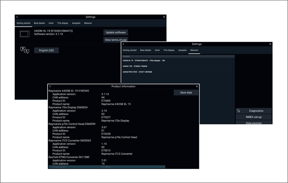
The Getting started menu contains hardware and software information for your MFD.
Learning resources
Video tutorials
Raymarine official channel on YouTube:
LightHouse ™ 3 tips and tricks:
Video Gallery:
Note:
|
Training courses
Raymarine regularly runs a range of in-depth training courses to help you make the most of your products. Visit the Training section of the Raymarine website for more information:
Appendix
NMEA 0183 sentence support
|
Sentence |
Description |
Transmit |
Receive |
|---|---|---|---|
|
APB |
Heading / Track controller pilot sentence “B” |
• |
• |
|
BWC |
Bearing & distance to waypoint — great circle |
• |
• |
|
BWR |
Bearing & distance to waypoint — rhumb line |
• |
• |
|
DBT |
Depth below transducer |
• |
• |
|
DPT |
Depth |
• |
• |
|
GGA |
GNSS (GPS) fix data |
• |
• |
|
GLL |
Geographic position lat/long |
• |
• |
|
GSA |
GNSS (GPS) DOP & active satellites |
• |
• |
|
GST |
GNSS (GPS) Pseudo Range Error Statistics |
• |
• |
|
GSV |
GNSS (GPS) satellites in view |
• |
• |
|
MTW |
Water temperature |
• |
• |
|
MWV |
Wind speed & angle |
• |
• |
|
RMB |
Recommended minimum navigation information |
• |
• |
|
RMC |
Recommended minimum specific GNSS (GPS) data |
• |
• |
|
RSD |
Radar system data |
• |
• |
|
TTM |
Tracked target message |
• |
• |
|
VHW |
Water speed and heading |
• |
• |
|
VLW |
Dual ground/water distance |
• |
• |
|
VTG |
COG (Course Over Ground) & ground speed |
• |
• |
|
ZDA |
Time & date |
• |
• |
NMEA 2000 PGN support
|
PGN |
Description |
Transmit |
Receive |
|---|---|---|---|
|
59392 |
ISO Acknowledgment |
• |
• |
|
59904 |
ISO Request |
• |
• |
|
60928 |
ISO Address Claim |
• |
• |
|
126208 |
NMEA - Request group function |
• |
• |
|
126464 |
Receive/Transmit PGN's group function |
• |
• |
|
126992 |
System Time |
• |
• |
|
126996 |
Product Information |
• |
• |
|
127237 |
Heading/Track Control |
• |
|
|
127245 |
Rudder |
• |
|
|
127250 |
Vessel Heading |
• |
• |
|
127488 |
Engine Parameters, Rapid Update |
• |
|
|
127489 |
Engine Parameters, Dynamic |
• |
|
|
127493 |
Transmission Parameters, Dynamic |
• |
|
|
127496 |
Trip Parameters, Vessel |
• |
|
|
127497 |
Trip Parameters, Engine |
• |
|
|
127498 |
Engine Parameters, Static |
• |
|
|
127505 |
Fluid Level |
• |
|
|
127506 |
DC Charge Status |
• |
|
|
128259 |
Speed |
• |
• |
|
128267 |
Water Depth |
• |
• |
|
128275 |
Distance Log |
• |
• |
|
129025 |
Position, Rapid Update |
• |
• |
|
129026 |
COG & SOG, Rapid Update |
• |
• |
|
129029 |
GNSS Position Data |
• |
• |
|
129033 |
Time & Date |
• |
• |
|
129038 |
AIS Class A Position Report |
• |
|
|
129039 |
AIS Class B Position Report |
• |
|
|
129040 |
AIS Class B Extended Position Report |
• |
|
|
129041 |
AIS Aids to Navigation (AtoN) Report |
• |
|
|
129044 |
Datum |
• |
• |
|
129283 |
Cross Track Error |
• |
• |
|
129284 |
Navigation Data |
• |
• |
|
129291 |
Set & Drift, Rapid Update |
• |
• |
|
129301 |
Time to/from Mark |
• |
|
|
129539 |
GNSS DOPs |
• |
|
|
129540 |
GNSS Sats in View |
• |
• |
|
129545 |
GNSS RAIM Output |
• |
|
|
129550 |
GNSS Differential Correction Receiver Interface |
• |
|
|
129551 |
GNSS Differential Correction Receiver Signal |
• |
|
|
129793 |
AIS UTC and Date Report |
• |
|
|
129794 |
AIS Class A Static and Voyage Related Data |
• |
|
|
129798 |
AIS SAR Aircraft Position Report |
• |
|
|
129801 |
AIS Addressed Safety Related Message |
• |
|
|
129802 |
AIS Safety Related Broadcast Message |
• |
|
|
129808 |
DSC call information |
• |
|
|
129809 |
AIS Class B "CS" Static Report, Part A |
• |
|
|
129810 |
AIS Class B |
• |
|
|
129812 |
AIS Multi Slot Binary Message |
• |
• |
|
130306 |
Wind Data |
• |
• |
|
130310 |
Environmental Parameters |
• |
• |
|
130311 |
Environmental Parameters |
• |
|
|
130576 |
Small Craft Status |
• |
|
|
130577 |
Direction Data |
• |
• |
|
130578 |
Vessel Speed Components |
• |
Raymarine ® provides field programmability of the Device and System Instances within PGN 60928 which can be commanded via use of PGN 126208 as required by the latest NMEA 2000 standard.
Document change history
|
Document revision and (Date) |
Software version |
Changes |
|---|---|---|
|
81370–16 (06–2020) |
LH3.12 (R2) |
|
|
81370–15 (03–2020) |
LH3.12 (R1) |
|
|
81370–14 (10–2019) |
LH3.11 |
|
|
81370–13 (09–2019) |
LH3.10.71 |
|
|
81370–12 (07–2019) |
LH3.10 |
|
|
81370–11 (04–2019) |
LH3.9 |
|
|
81370–10 (12–2018) |
LH3.8 |
|
|
81370–9 (09–2018) |
LH3.7 |
|
|
81370–8 81370–7 (07–2018) |
LH3.6 |
|
|
81370–6 (06–2018) |
LH3.5 |
|
|
81370–5 (02–2018) |
LH3.4 |
|
|
81370–4 (11–2017) |
LH3.3 |
|
|
81370–3 (09–2017) |
LH3.2 |
|
|
81370–2 (07–2017) |
LH3.1 |
|
|
81370–1 (04–2017) |
LH3.0 |
First release. |
Hardware compatibility
|
Software version |
Hardware |
|---|---|
|
LH3.12 |
|
|
LH3.11 |
|
|
LH3.10.71 |
|
|
LH3.9 |
|
|
LH3.8 |
|
|
LH3.7 |
|
|
LH3.6 |
|
|
LH3.5 |
|
|
LH3.4 |
|
|
LH3.3 |
|
|
LH3.2 |
|
|
LH3.1 |
|
|
LH3.0 |
|