Axiom Installation instructions
Notices
Trademark and patents notice
Raymarine, Tacktick, Clear Pulse, Truzoom, SeaTalk, SeaTalkhs , SeaTalkng, and Micronet, are registered or claimed trademarks of Raymarine Belgium.
FLIR, LightHouse, DownVision, SideVision, RealVision, HyperVision, Dragonfly, Element, Quantum, Axiom, Instalert, Infrared Everywhere, The World’s Sixth Sense and ClearCruise are registered or claimed trademarks of FLIR Systems, Inc.
All other trademarks, trade names, or company names referenced herein are used for identification only and are the property of their respective owners.
This product is protected by patents, design patents, patents pending, or design patents pending.
Fair Use Statement
You may print no more than three copies of this manual for your own use. You may not make any further copies or distribute or use the manual in any other way including without limitation exploiting the manual commercially or giving or selling copies to third parties.
Software updates

|
Check the Raymarine website for the latest software releases for your product. |
Product documentation

|
The latest versions of all English and translated documents are available to download in PDF format from the website: www.raymarine.com/manuals. Please check the website to ensure you have the latest documentation. |
Publication copyright
Copyright ©2020 Raymarine UK Ltd. All rights reserved.
Important information

|
Warning: Product installation and operation |
|
color.png)
|
Warning: High voltage |
|
This product contains high voltage. Adjustments require specialized service procedures and tools only available to qualified
service technicians. There are no user serviceable parts or adjustments. The operator should never remove the cover or attempt
to service the product.
|
Disclaimers
Raymarine does not warrant that this product is error-free or that it is compatible with products manufactured by any person or entity other than Raymarine.
This product uses digital chart data, and electronic information from Global Navigation Satellite Systems (GNSS) which may contain errors. Raymarine does not warrant the accuracy of such information and you are advised that errors in such information may cause the product to malfunction. Raymarine is not responsible for damages or injuries caused by your use or inability to use the product, by the interaction of the product with products manufactured by others, or by errors in chart data or information utilized by the product and supplied by third parties.
This product supports electronic charts provided by third party suppliers which may be embedded or stored on memory card. Use of such charts is subject to the supplier’s End-User Licence Agreement.
RF exposure
This equipment complies with FCC / ISED RF exposure limits for general population / uncontrolled exposure. The wireless LAN / Bluetooth antenna is mounted behind the front facia of the display. This equipment should be installed and operated with a minimum distance of 1 cm (0.39 in) between the device and the body. This transmitter must not be co-located or operating in conjunction with any other antenna or transmitter, except in accordance with FCC multi-transmitter product procedures.
Compliance Statement (Part 15.19)
This device complies with Part 15 of the FCC Rules. Operation is subject to the following two conditions:
- This device may not cause harmful interference.
- This device must accept any interference received, including interference that may cause undesired operation.
FCC Interference Statement (Part 15.105 (b))
These limits are designed to provide reasonable protection against harmful interference in a residential installation. This equipment generates, uses, and can radiate radio frequency energy and, if not installed and used in accordance with the instructions, may cause harmful interference to radio communications. However, there is no guarantee that interference will not occur in a particular installation. If this equipment does cause harmful interference to radio or television reception, which can be determined by turning the equipment off and on, the user is encouraged to try to correct the interference by one of the following measures:
- Reorient or relocate the receiving antenna.
- Increase the separation between the equipment and receiver.
- Connect the equipment into an outlet on a circuit different from that to which the receiver is connected.
- Consult the dealer or an experienced radio / TV technician for help.
Innovation, Science and Economic Development Canada (ISED)
Operation is subject to the following two conditions:
- This device may not cause interference; and
- This device must accept any interference, including interference that may cause undesired operation of the device.
This Class B digital apparatus complies with Canadian ICES-003.
Innovation, Sciences et Développement économique Canada (Français)
Son fonctionnement est soumis aux deux conditions suivantes:
- cet appareil ne doit pas causer d'interférence, et
- cet appareil doit accepter toute interférence, notamment les interférences qui peuvent affecter son fonctionnement.
Cet appareil numérique de la classe B est conforme à la norme NMB-003 du Canada.
Japanese approvals
In the frequency band used for this device, campus radio stations (radios stations that require a license) and specified low power radio stations (radio stations that do not require license) for mobile identification and amateur radio stations (radio stations that require license) used in industries such as microwave ovens, scientific, medical equipment devices and production line of other factories are also being operated.
- Before using this device, please make sure that campus radio stations and specified low power radio stations for mobile identification and amateur radio stations are not being operated nearby.
- In case there is any case of harmful interference to campus radio stations for mobile identification caused by this device, please immediately change the frequency used or stop the transmission of radio waves and then consult about the measures to avoid interference (for example, the installation of partitions) through the contact information below.
- Besides, when in trouble, such as when there is any case of harmful interference to specified low power radio stations for mobile identification or amateur radio stations caused by this device, please consult through the following contact information.
Contact information: Please contact your local authorized Raymarine dealer.
MSIP Warning Statement for Radio Devices (Korea only)
- 제작자 및 설치자는 해당 무선설비가 전파혼신 가능성이 있으므로 안전 인명과 관련된
- 서비스는 할 수 없음을 사용자 설명서 등을 통하여 운용자 및 사용자에게 충분히 알릴 것
- 법에 의해 전 방향 전파 발사 및 동일한 정보를 동시에 여러 곳으로 송신하는 점-대-다지점 서비스에의 사용은 금지되어 있습니다.
Declaration of Conformity
FLIR Belgium BVBA declares that the radio equipment types Axiom multifunction displays, part numbers E70363, E70363–DISP, E70364, E70364–01, E70364–02, E70364–DISP, E70365, E70365–03, E70365–DISP, E70366, E70366–DISP, E70367, E70367–02, E70367–03, E70367–DISP, E70368, E70368–DISP, E70369, E70369–03, E70369–DISP, are in compliance with the Radio Equipment Directive 2014/53/EU.
The original Declaration of Conformity certificate may be viewed on the relevant product page at www.raymarine.com/manuals.
Product disposal
The Waste Electrical and Electronic Equipment (WEEE) Directive requires the recycling of waste electrical and electronic equipment which contains materials, components and substances that may be hazardous and present a risk to human health and the environment when WEEE is not handled correctly.

|
Equipment marked with the crossed-out wheeled bin symbol indicates that the equipment should not be disposed of in unsorted household waste. Local authorities in many regions have established collection schemes under which residents can dispose of waste electrical and electronic equipment at a recycling center or other collection point. For more information about suitable collection points for waste electrical and electronic equipment in your region, refer to the Raymarine website: www.raymarine.eu/recycling. |
Warranty registration
To register your Raymarine product ownership, please visit www.raymarine.com and register online.
It is important that you register your product to receive full warranty benefits. Your unit package includes a bar code label indicating the serial number of the unit. You will need this serial number when registering your product online. You should retain the label for future reference.
Technical accuracy
To the best of our knowledge, the information in this document was correct at the time it was produced. However, Raymarine cannot accept liability for any inaccuracies or omissions it may contain. In addition, our policy of continuous product improvement may change specifications without notice. As a result, Raymarine cannot accept liability for any differences between the product and this document. Please check the Raymarine website (www.raymarine.com) to ensure you have the most up-to-date version(s) of the documentation for your product.
Document and product information
Product documentation
All documents are available to download as PDFs from www.raymarine.com
Documentation
LightHouse ™ 3 MFD Operation instructions
For operation instructions for your product please refer to the LightHouse ™ 3 MFD Operation instructions.

|
The Basic (81369) and Advanced (81370) LightHouse ™ 3 Operation Instructions can be downloaded from the Raymarine website: www.raymarine.com/manuals. Please check the website to ensure you have the latest documentation. |
Applicable products
Axiom ™ Multifunction Displays

| Product number | Name | Description |
|---|---|---|
| E70363 | Axiom ™ 7 | 7” MFD Chartplotter |
| E70363–DISP | Axiom ™ 7 | 7” MFD Chartplotter (supplied with Rear mount kit only) |
| E70364 | Axiom ™ 7 DV | 7” MFD with built-in DownVision ™ sonar module |
| E70364–01 | Axiom ™ 7 DV (including CPT–S transom transducer) | 7” MFD with built-in DownVision ™ sonar module |
| E70364–02 | Axiom ™ 7 DV (including CPT–100DVS transducer) | 7” MFD with built-in DownVision ™ sonar module |
| E70364–DISP | Axiom ™ 7 DV | 7” MFD with built-in DownVision ™ sonar module (supplied with Rear mount kit only) |
| E70365 | Axiom ™ 7 RV 3D | 7” MFD with built-in RealVision ™ 3D sonar module |
| E70365–03 | Axiom ™ 7 RV 3D (including RV–100 transom transducer) | 7” MFD with built-in RealVision ™ 3D sonar module |
| E70365–DISP | Axiom ™ 7 RV 3D | 7” MFD with built-in RealVision ™ 3D sonar module (supplied with Rear mount kit only) |
| E70366 | Axiom ™ 9 | 9” MFD Chartplotter |
| E70366–DISP | Axiom ™ 9 | 9” MFD Chartplotter (supplied with Rear mount kit only) |
| E70367 | Axiom ™ 9 RV 3D | 9” MFD with built-in RealVision ™ 3D sonar module |
| E70367–02 | Axiom ™ 9 RV 3D (including CPT–100DVS transducer) | 9” MFD with built-in RealVision ™ 3D sonar module |
| E70367–03 | Axiom ™ 9 RV 3D (including RV–100 transom transducer) | 9” MFD with built-in RealVision ™ 3D sonar module |
| E70367–DISP | Axiom ™ 9 RV 3D | 9” MFD with built-in RealVision ™ 3D sonar module (supplied with Rear mount kit only) |
| E70368 | Axiom ™ 12 | 12” MFD Chartplotter |
| E70368–DISP | Axiom ™ 12 | 12” MFD Chartplotter (supplied with Rear mount kit only) |
| E70369 | Axiom ™ 12 RV 3D | 12” MFD with built-in RealVision ™ 3D sonar module |
| E70369–03 | Axiom ™ 12 RV 3D (including RV–100 transom transducer) | 12” MFD with built-in RealVision ™ 3D sonar module |
| E70369–DISP | Axiom ™ 12 RV 3D | 12” MFD with built-in RealVision ™ 3D sonar module (supplied with Rear mount kit only) |
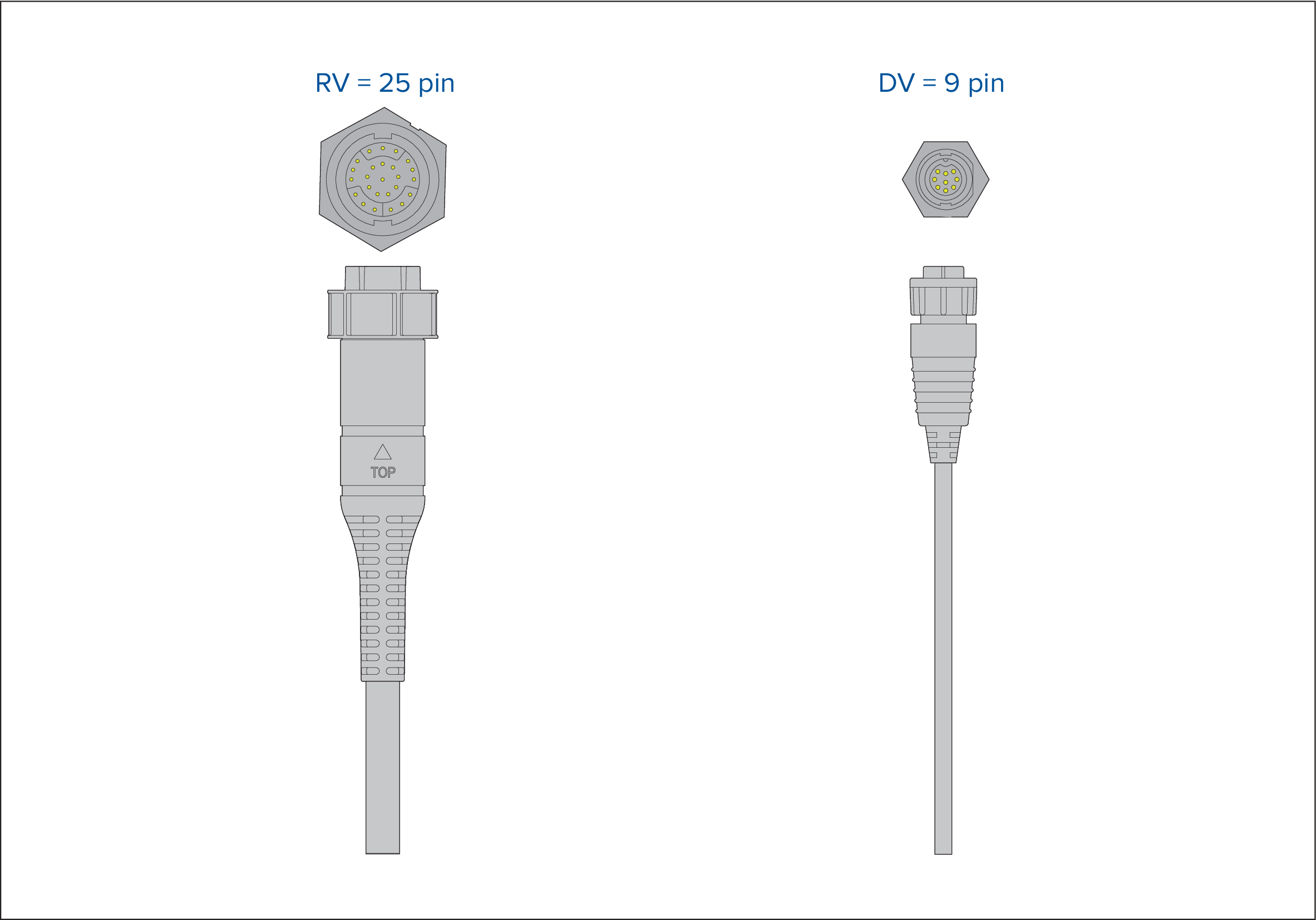
Compatible transducers for Axiom ™ MFDs
Depending on your MFD variant you can connect the following transducer types directly to your MFD:
Axiom DV (Using 9–pin connection)
- DownVision ™ transducers
- CHIRP conical beam transducers that utilize the 9 pin DownVision ™ connector.
- Other transducers can be connected using available adaptor cables. Refer to Spares and accessories for a list of available adaptor cables. Refer to the Raymarine ® website for compatible transducers: www.raymarine.com/transducers.
Axiom RV (Using 25–pin connection)
- RealVision ™ 3D transducers
- DownVision ™ transducers using available adaptor cables. Refer to Spares and accessories for a list of available adaptor cables.
- CHIRP conical beam transducers using available adaptor cables. Refer to Spares and accessories for a list of available adaptor cables.
- Non-CHIRP transducer can be connected using available adaptor cables. Refer to Spares and accessories for a list of available adaptor cables. Refer to the Raymarine ® website for compatible transducers: www.raymarine.com/transducers.
Axiom Chartplotter
Axiom Chartplotter only variants require a networked Sonar module to enable Sonar.
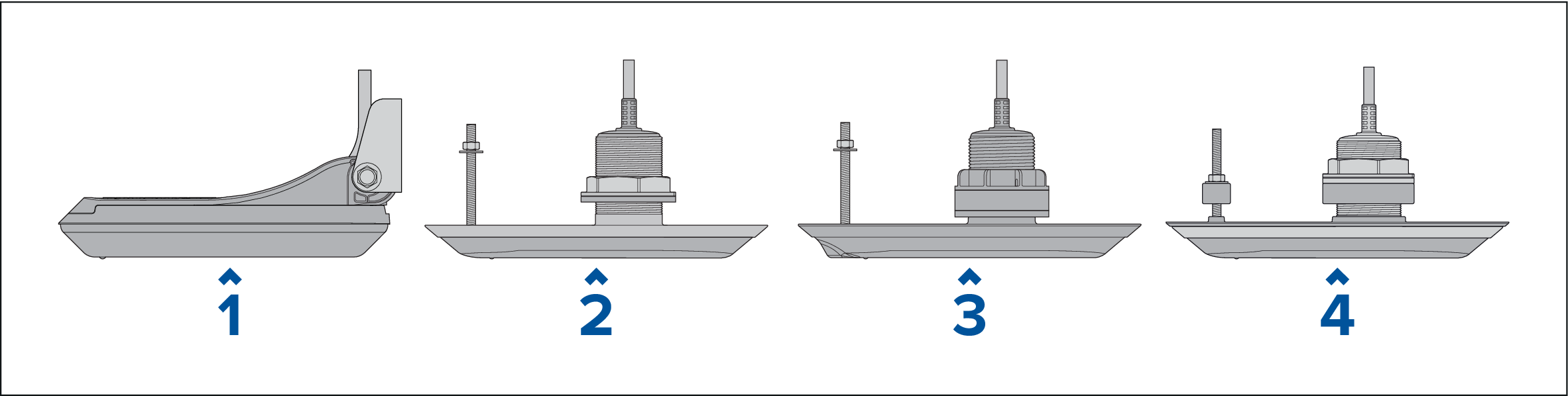
RealVision transducers
|
1 |
|
|
2 |
|
|
3 |
|
|
4 |
|
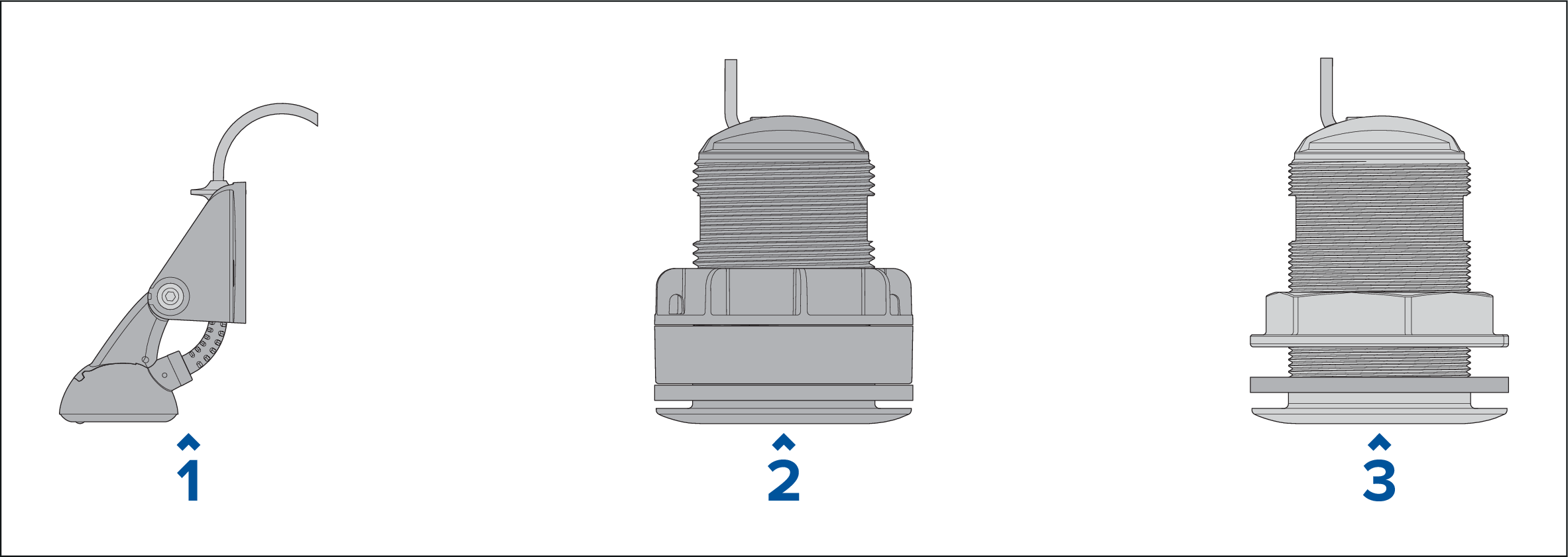
DownVision ™ transducers
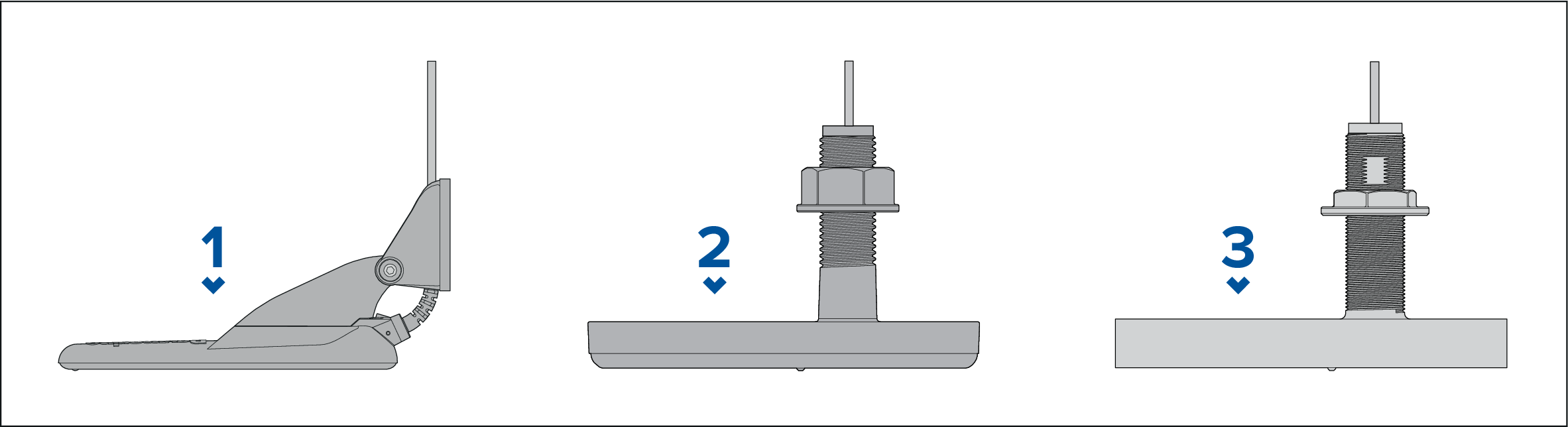
CHIRP conical beam transducers (using DownVision ™ type connector)
CPT-S transducers use CHIRP sonar technology to produce a conical-shaped sonar beam.
| Note: CPT-S transducers do NOT offer DownVision ™ channels. |
|
1 |
|
|
2 |
|
|
3 |
|
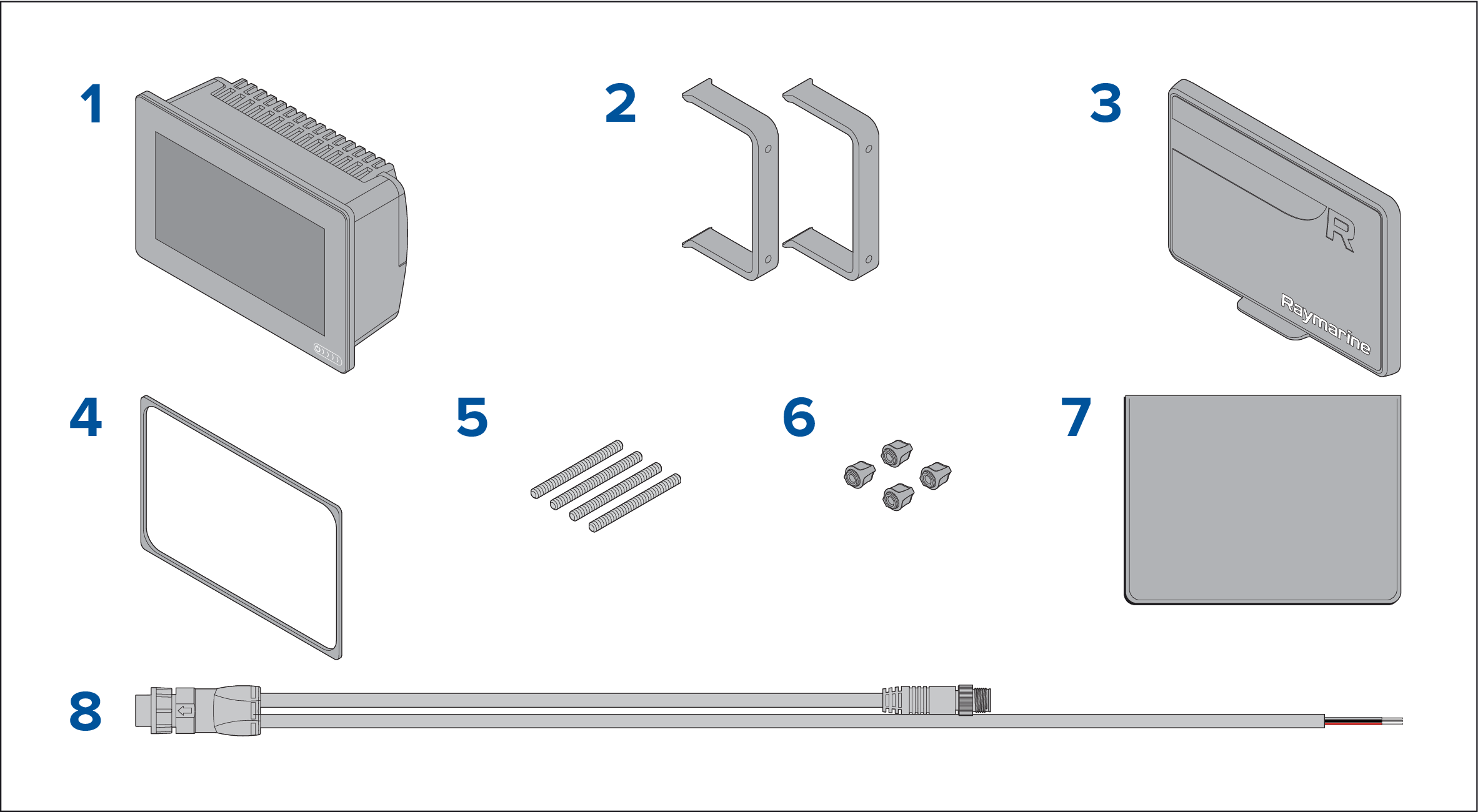
Parts supplied - Axiom 7
The parts listed are supplied with the following product numbers: E70363, E70364 and E70365.

- MFD (supplied with Trunnion adaptor fitted)
- Trunnion bracket
- Trunnion knobs x 2
- Suncover — Trunnion mount
- Panel mount gasket for surface/flush mounting
- M5x58 Threaded studs x 4
- M5 Thumb nuts x 4
- Documentation pack
- Power/NMEA 2000 cable (with 1.5 m (4.92 ft) power lead and 0.5 m (1.64 ft) NMEA 2000 lead).
E70364–01 is also supplied with a CPT-S transom transducer and associated fittings.
E70364–02 is also supplied with a DownVision ™ CPT-100DVS transducer and associated fittings.
E70365–03 is also supplied with a RealVision ™ 3D RV-100 transducer and associated fittings.
Parts Supplied - Axiom 7 (DISP)
The parts listed are supplied with the following product numbers: E70363–DISP, E70364–DISP and E70365–DISP.
- MFD
- Rear mount brackets x 2
- Suncover — Surface mount
- Panel mount gasket for surface/flush mounting
- M5x58 Threaded studs x 4
- M5 Thumb nuts x 4
- Documentation pack
- Power/NMEA 2000 cable (with 1.5 m (4.92 ft) power lead and 0.5 m (1.64 ft) NMEA 2000 lead).
Parts supplied - Axiom 9 and 12
The parts listed are supplied with the following product numbers: E70366, E70367, E70368 and E70369.

- MFD
- Trunnion bracket
- Trunnion knobs x 2
- Suncover
- Panel mount gasket for surface/flush mounting
-
Rear mounting brackets:
- supplied with 9” MFD
- supplied with 12” MFD
- Documentation pack
- Power / NMEA 2000 cable (with 1.5 m (4.92 ft) power lead and 0.5 m (1.64 ft) NMEA 2000 lead).
- M5x58 Threaded studs x 4
- M5 Thumb nuts x 4
E70367–02 is also supplied with a DownVision ™ CPT-100DVS transducer and associated fittings.
E70367–03 is also supplied with a RealVision ™ 3D RV-100 transducer and associated fittings.
E70369–03 is also supplied with a RealVision ™ 3D RV-100 transducer and associated fittings.
Parts supplied - Axiom 9 and 12 (DISP)
The parts listed are supplied with the following product numbers: E70366–DISP, E70367–DISP, E70368–DISP and E70369–DISP.

- MFD
- Panel mount gasket for surface / flush mounting
- Suncover
- M5x58 Threaded studs x 4
- M5 Thumb nuts x 4
-
Rear mounting brackets:
- supplied with 9” MFD
- supplied with 12” MFD
- Documentation pack
- Power/NMEA 2000 cable (with 1.5 m (4.92 ft) power lead and 0.5 m (1.64 ft) NMEA 2000 lead).
Installation
Selecting a location
Caution: Product weight |
|
|
|
Warning: Switch off power supply |
|
Ensure the vessel’s power supply is switched OFF before starting to install this product. Do NOT connect or disconnect equipment
with the power switched on, unless instructed in this document.
|
|
|
Warning: Potential ignition source |
|
This product is NOT approved for use in hazardous/flammable atmospheres. Do NOT install in a hazardous/flammable atmosphere (such as in an engine room or near fuel tanks). |
General location requirements
Key factors which can affect product performance are:
-
Ventilation — To ensure adequate airflow:
Any specific requirements for each system component are provided later in this chapter.
- Ensure that product is mounted in a compartment of suitable size.
- Ensure that ventilation holes are not obstructed. Allow adequate separation of all equipment.
- Mounting surface — Ensure product is adequately supported on a secure surface. Do not mount units or cut holes in places which may damage the structure of the vessel.
-
Cabling — Ensure the product is mounted in a location which allows proper routing, support and connection of cables:
- Minimum bend radius of 100 mm (3.94 in) unless otherwise stated.
- Use cable clips to prevent stress on connectors.
- If your installation requires multiple ferrites to be added to a cable then additional cable clips should be used to ensure the extra weight of the cable is supported.
- Water ingress — The product is suitable for mounting both above and below decks. Although the unit is waterproof, it is good practice to locate it in a protected area away from prolonged and direct exposure to rain and salt spray.
- Electrical interference — Select a location that is far enough away from devices that may cause interference, such as motors, generators and radio transmitters / receivers.
- Power supply — Select a location that is as close as possible to the vessel’s DC power source. This will help to keep cable runs to a minimum.
EMC installation guidelines
Raymarine equipment and accessories conform to the appropriate Electromagnetic Compatibility (EMC) regulations, to minimize electromagnetic interference between equipment and minimize the effect such interference could have on the performance of your system
Correct installation is required to ensure that EMC performance is not compromised.
| Note: In areas of extreme EMC interference, some slight interference may be noticed on the product. Where this occurs the product and the source of the interference should be separated by a greater distance. |
For optimum EMC performance we recommend that wherever possible:
-
Raymarine equipment and cables connected to it are:
- At least 1 m (3.3 ft) from any equipment transmitting or cables carrying radio signals e.g. VHF radios, cables and antennas. In the case of SSB radios, the distance should be increased to 2 m (6.6 ft).
- More than 2 m (6.6 ft) from the path of a radar beam. A radar beam can normally be assumed to spread 20 degrees above and below the radiating element.
- The product is supplied from a separate battery from that used for engine start. This is important to prevent erratic behavior and data loss which can occur if the engine start does not have a separate battery.
- Raymarine specified cables are used.
- Cables are not cut or extended, unless doing so is detailed in the installation manual.
|
Note:
Where constraints on the installation prevent any of the above recommendations, always ensure the maximum possible separation between different items of electrical equipment, to provide the best conditions for EMC performance throughout the installation. |
RF interference
Some common examples of such external equipment include LED lighting (e.g.: navigation lights, searchlights and floodlights, interior and exterior lights) and terrestrial TV tuners.
To minimize interference from such equipment:
- Keep it as far away from GNSS (GPS), AIS or VHF products and their antennas as possible.
- Ensure that any power cables for external equipment are not entangled with the power or data cables for these devices.
- Consider fitting one or more high frequency suppression ferrites to the EMI-emitting device. The ferrite(s) should be rated to be effective in the range 100 MHz to 2.5 GHz, and should be fitted to the power cable and any other cables exiting the EMI-emitting device, as close as possible to the position where the cable exits the device.
Compass safe distance
When choosing a suitable location for the product you should aim to maintain the maximum possible distance from any compasses. Typically this distance should be at least 1 m (3.3 ft) in all directions. However for some smaller vessels it may not be possible to locate the product this far away from a compass. In this situation, when choosing the installation location for your product, ensure that the compass is not affected by the product when it is in a powered state.
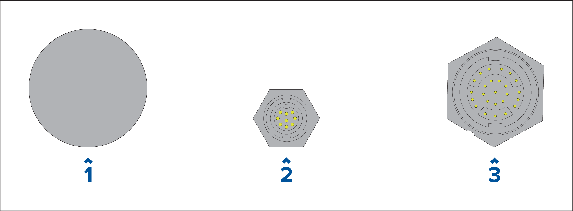
GNSS (GPS) location requirements
Mounting location
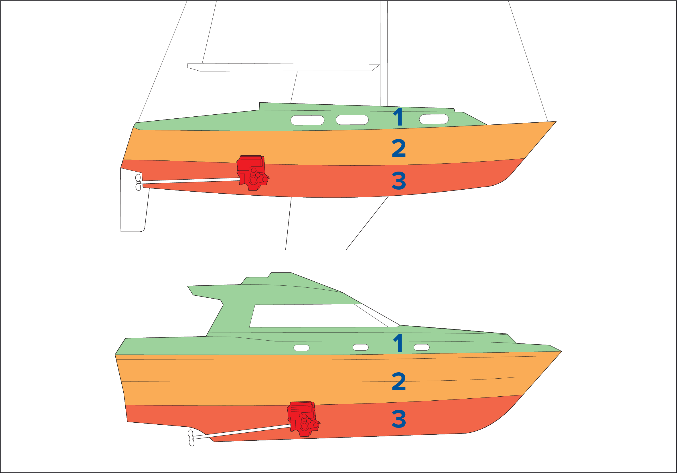
|
1 |

|
This location provides optimal performance (above decks). |
|
2 |

|
In this location, performance may be less effective. |
|
3 |

|
This location is NOT recommended. |
Vessel construction
The construction of your vessel can have an impact on performance. For example, the proximity of heavy structures such as a structural bulkhead, or the interior of larger vessels may result in a reduced signal. The construction materials can also have an impact. In particular, steel, aluminium or carbon surfaces can impact performance. Before locating equipment with an internal antenna below decks, or on a steel, aluminium or carbon construction vessel or surface, seek professional assistance.
Prevailing conditions
The weather and location of the vessel can affect performance. Typically calm clear conditions provide a more accurate position fix. Vessels at extreme northerly or southerly latitudes may also receive a weaker signal. An antenna mounted below decks will be more susceptible to performance issues related to the prevailing conditions.
Touchscreen location requirements
Wireless location requirements
Distance
The distance between wireless products should always be kept to a minimum. Do not exceed the maximum stated range of your wireless product (maximum range will vary for each device).
Wireless performance degrades over distance, so products farther away will receive less network bandwidth. Products installed close to their maximum wireless range may experience slow connection speeds, signal dropouts, or not being able to connect at all.
Line of sight
For best results the wireless product should have a clear, direct line of sight to the product it will be connected to. Any physical obstructions can degrade or even block the wireless signal.
The construction of your vessel can also have an impact on wireless performance. For example, metal structural bulkheads and roofing will reduce — and in certain situations — block the wireless signal.
If the wireless signal passes through a bulkhead containing power cables this can also degrade wireless performance.
Reflective surfaces such as metal surfaces, some types of glass and even mirrors can drastically affect performance or even block the wireless signal.
Interference and other equipment
Wireless products should be installed at least 1m (3 ft) away from:
- Other wireless-enabled products.
- Transmitting products that send wireless signals in the same frequency range.
- Other electrical, electronic or electromagnetic equipment that may generate interference.
Interference from other people’s wireless devices can also cause interference with your products. You can use a third-party wireless analyzer tool / smartphone app to assess the best wireless channel to use (e.g. a channel not in use or one used by the least number of devices).
Viewing angle considerations
As display contrast and color are affected by the viewing angle, It is recommended that you temporarily power up the display, prior to installation, to enable you to best judge which location provides the optimum viewing angle.
For the viewing angles for your product refer to Technical specification
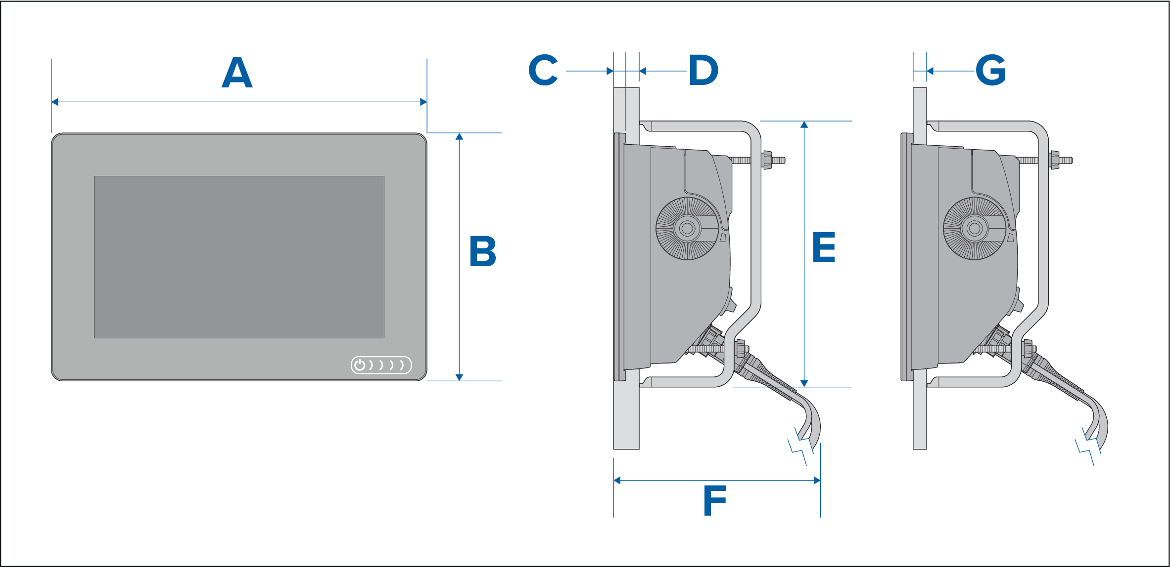
Product dimensions
Axiom 7 trunnion mount dimensions

Axiom 7 surface and flush mount dimensions
Using adaptor bracket

Using Rear mount kit

|
A |
201.1 mm (7.92 in) |
|
B |
133 mm (5.24 in) |
|
C |
8 mm (0.32 in) |
|
D |
|
|
E |
|
|
F |
73 mm ( 2.87 in) |
|
G |
132 mm (5.2 in) |
Axiom 9 and 12 trunnion mount dimensions

|
Axiom ™ 9 |
Axiom ™ 12 |
|
|---|---|---|
|
A |
265.03 mm (10.43 in) |
314 mm (12.36 in) |
|
B |
187.81 (7.39 in) |
226.72 mm (8.93 in) |
|
C |
76.71 mm (3.02 in) |
76.2 mm (3 in) |
|
D |
65 mm (2.56 in) |
65 mm (2.56 in) |
|
E |
|
|
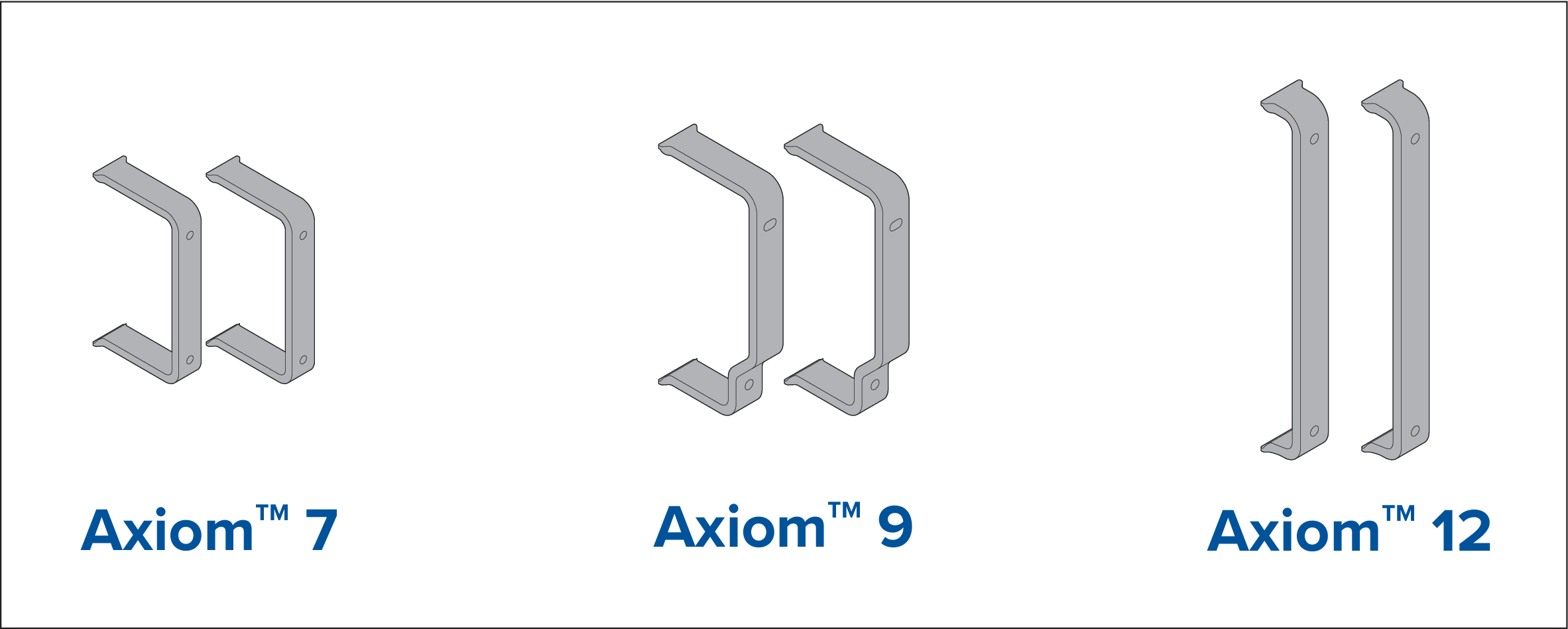
Axiom 9 and 12 surface and flush mount dimensions
| Axiom ™ 9 | Axiom ™ 12 | |
|---|---|---|
|
A |
244.08 mm (9.64 in) |
314 mm (12.36 in) |
|
B |
157.78 mm (6.21 in) |
217 mm (8.54 in) |
|
C |
8 mm (0.31 in) |
|
|
D |
27.05 mm (1.06 in) Maximum |
|
|
E |
157 mm 6.18 in) |
222 mm (8.74 in) |
|
F |
178 mm (7.01 in) |
|
|
G |
19.05 mm (0.75 in) Maximum |
|
|
Note:
The rear mount brackets shown in the illustration are supplied with the Axiom ™ 9, The brackets supplied with the Axiom ™ 12 look different. |
Mounting options

Legacy MFD adaptor plates are also available to enable you to easily swap out older MFDs for new Axiom MFDs, please refer to Spares and accessories for a list of available adaptors.
Bracket (Trunnion) mounting

| Note: The illustration depicts an Axiom ™ 7 being mounted on a plastic trunnion bracket. The trunnion bracket supplied with the Axiom ™ 9 and Axiom ™ 12 are made from metal and so look different than the trunnion shown. A metal trunnion bracket is also available for the Axiom ™ 7 as an accessory; Part number: R70524. |
Axiom 7 flush and surface mounting
Removing the trunnion adaptor Axiom ™ 7

Surface or Flush mounting Axiom ™ 7 only

| Important: In above decks, flush mount installations, marine grade silicone should be used to seal the gap between the edge of the mounting surface and the edge of the MFD. |
| Important: To prevent potential damage to the unit, do NOT overtighten the thumb nuts. Hand tighten only. |
| Note: The suncover provided in the box is for use in Trunnion bracket installations, when Surface mounting the product accessory suncover R70527 is required. No suncover is available for Flush mount installations. |
Surface or flush mounting using the Rear Mount Kit

| Important: In above decks, flush mount installations, marine grade silicone should be used to seal the gap between the edge of the mounting surface and the edge of the MFD. |
| Important: To prevent potential damage to the unit, do NOT overtighten the thumb nuts. Hand tighten only. |
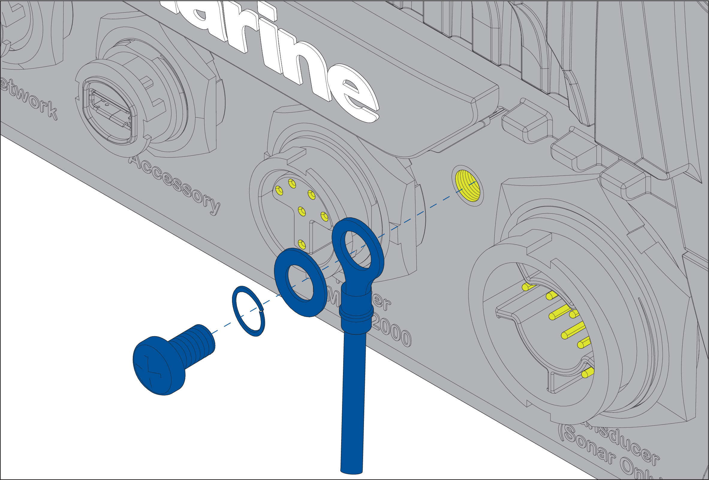
Connections
Connections overview

MFD connections
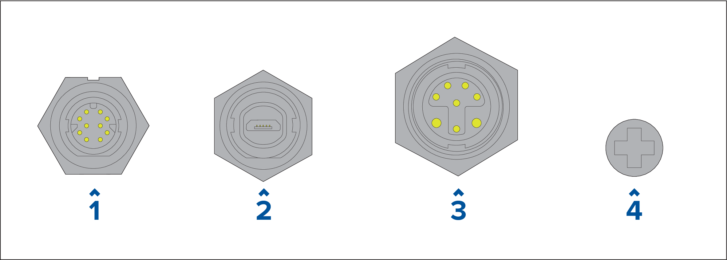
- Network connection — Connects to RayNet network or device. Refer to Spares and Accessories for available cables.
- Accessory connection — Connects to Remote Card Reader (RCR) accessory.
- Power / NMEA 2000 connection — Connects to 12 V DC power supply / NMEA 2000 or SeaTalkng ® backbone.
- Optional grounding point — Connects to Vessel RF ground, or negative battery terminal. Refer to Grounding — optional dedicated drain wire section for details.
Transducer connections
Depending on MFD variant different transducer connections are available
- No connection — An external sonar module is required for transducer connections.
- DV Transducer connection — Connects to DownVision ™ transducers.
- RV Transducer connection — Connects to RealVision ™ 3D transducers.
Connecting cables
Power connection
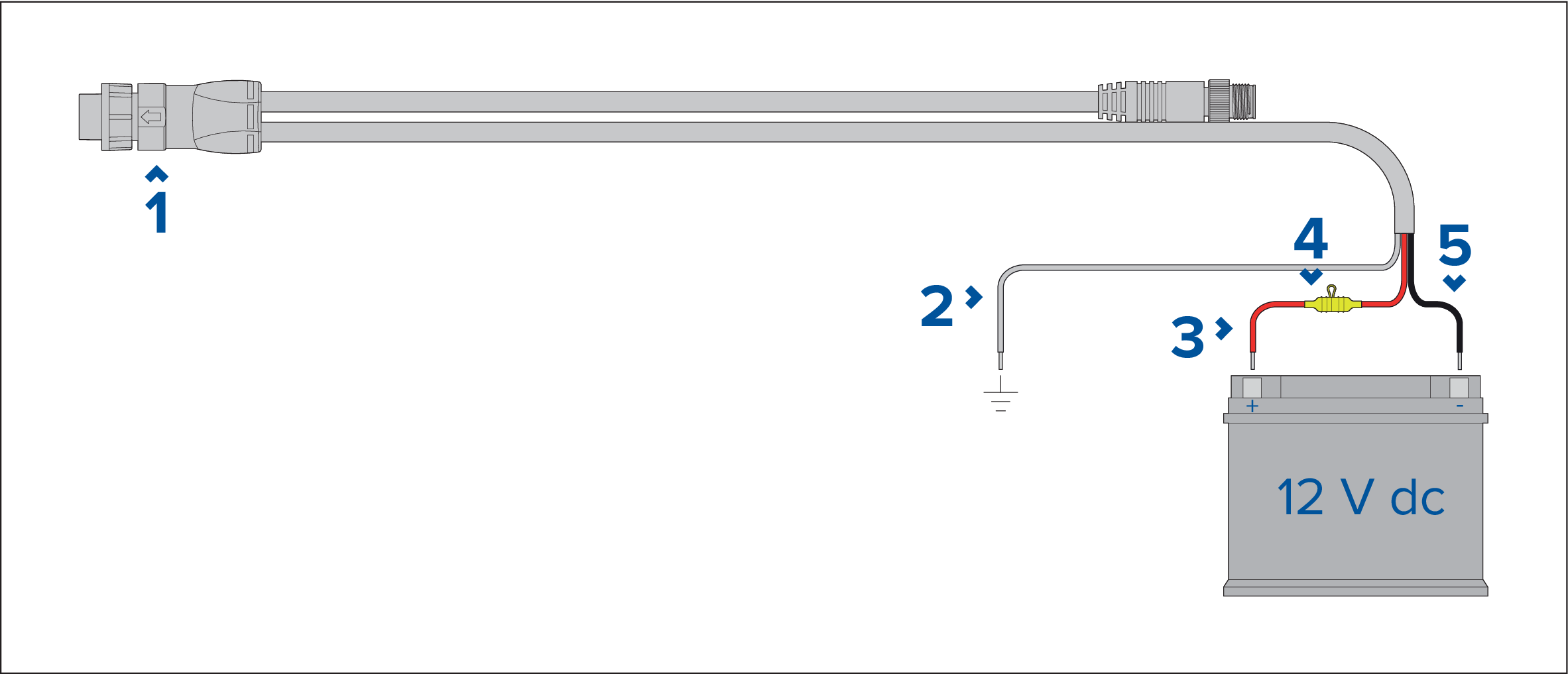
- Power/NMEA 2000 cable connects to the rear of the display.
- Ground wire connects to RF ground point, if no ground point is available connect to the battery negative (-) terminal.
- Positive (Red) wire connects to battery positive (+) terminal.
- Waterproof fuse holder with 7 A fuse must be fitted (not supplied)
- Negative wire connects to battery negative (-) terminal.
In-line fuse and thermal breaker ratings
Note:
|
Caution: Power supply protection |
|
When installing this product ensure the power source is adequately protected by means of a suitably-rated fuse or automatic
circuit breaker.
|
Power distribution
- The product is supplied with a power cable, either as a separate item or a captive cable permanently attached to the product. Only use the power cable supplied with the product. Do NOT use a power cable designed for, or supplied with, a different product.
- Refer to the Power connection section for more information on how to identify the wires in your product’s power cable, and where to connect them.
- See below for more information on implementation for some common power distribution scenarios:
Important:
|
Implementation — connection to distribution panel (Recommended)
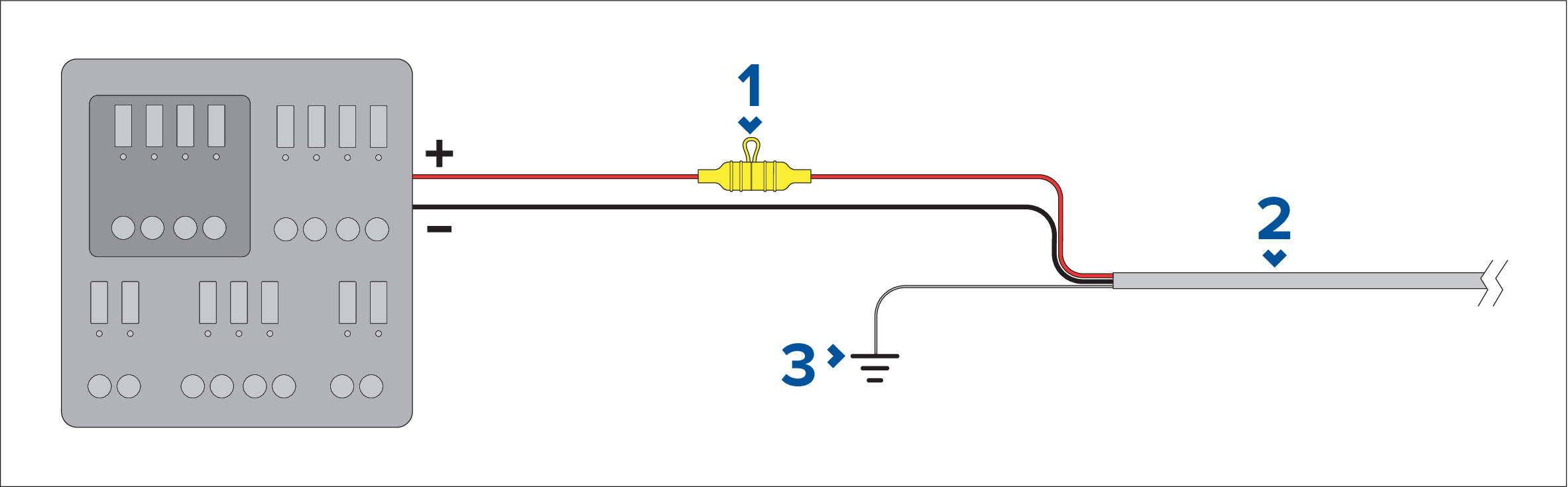
|
1 |
Waterproof fuse holder containing a suitably-rated inline fuse must be fitted. For suitable fuse rating, refer to: In-line fuse and thermal breaker ratings. |
|
2 |
Product power cable. |
|
3 |
Drain wire connection point. |
- It is recommended that the supplied power cable is connected to a suitable breaker or switch on the vessel's distribution panel or factory-fitted power distribution point.
- The distribution point should be fed from the vessel’s primary power source by 8 AWG (8.36 mm2) cable.
-
Ideally, all equipment should be wired to individual suitably-rated thermal breakers or fuses, with appropriate circuit protection.
Where this is not possible and more than 1 item of equipment shares a breaker, use individual in-line fuses for each power
circuit to provide the necessary protection.
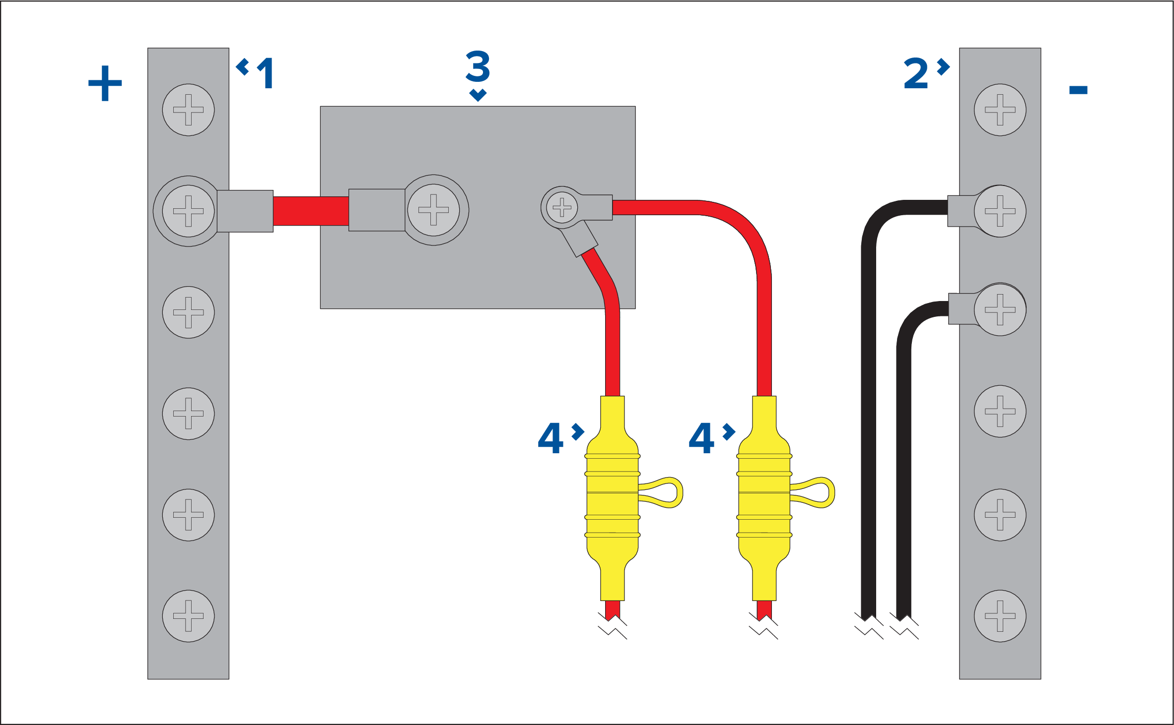
1
Positive (+) bar
2
Negative (-) bar
3
Circuit breaker
4
Waterproof fuse holder containing a suitably-rated inline fuse must be fitted. For suitable fuse rating, refer to: In-line fuse and thermal breaker ratings.
|
Important:
Observe the recommended fuse / breaker ratings provided in the product’s documentation, however be aware that the suitable fuse / breaker rating is dependent on the number of devices being connected. |
Implementation — direct connection to battery
- Where connection to a power distribution panel is not possible , the power cable supplied with your product may be connected directly to the vessel's battery, via a suitably rated fuse or breaker.
- The power cable supplied with your product may NOT include a separate drain wire. If this is the case, only the power cable’s red and black wires need to be connected.
- If the power cable is NOT supplied with a fitted inline fuse, you MUST fit a suitably rated fuse or breaker between the red wire and the battery’s positive terminal.
- Refer to the inline fuse ratings provided in the product’s documentation.
- If you need to extend the length of the power cable supplied with your product, ensure you observe the dedicated Power cable extensions advice provided in the product’s documentation.

|
1 |
Waterproof fuse holder containing a suitably-rated inline fuse must be fitted. For suitable fuse rating, refer to: In-line fuse and thermal breaker ratings. |
|
2 |
Product power cable. |
|
3 |
Drain wire connection point. |
Battery connection scenario A:
Suitable for a vessel with a common RF ground point. In this scenario, if your product’s power cable is supplied with a separate drain wire then it should be connected to the vessel’s common ground point.
Battery connection scenario B:
Suitable for a vessel without a common grounding point. In this case, if your product’s power cable is supplied with a separate drain wire then it should be connected directly to the battery’s negative terminal.
Power cable extension
If you need to extend the length of the power cable supplied with your product, ensure you observe the following advice:
- The power cable for each unit in your system should be run as a separate, single length of 2-wire cable from the unit to the vessel's battery or distribution panel.
- Ensure that the extension cable is of a sufficient gauge for the supply voltage and the total load of the device and the length of the cable run. Refer to the following table for typical minimum power cable wire gauges.
| Cable length in meters (feet) | Wire gauge in AWG (mm2) for 12 V supply | Wire gauge in AWG (mm2) for 24 V supply |
|---|---|---|
| <8 (<25) | 16 (1.31 mm2) | 18 (0.82 mm2) |
| 16 (50) | 14 (2.08 mm2) | 18 (0.82 mm2) |
| 24 (75) | 12 (3.31 mm2) | 16 (1.31 mm2) |
| >32 (>100) | 10 (5.26 mm2) | 16 (1.31 mm2) |
|
Important:
Be aware that some products in your system (such as sonar modules) can create voltage peaks at certain times, which may impact the voltage available to other products during the peaks. |
| Important: To ensure power cables (including any extension) are of a sufficient gauge, ensure that there is a continuous minimum voltage of 10.8 V dc at the end of the cable where it enters the product’s power connector, even with a fully flat battery at 11 V dc. (Do not assume that a flat battery is at 0 V dc. Due to the discharge profile and internal chemistry of batteries, the current drops much faster than the voltage. A “fully flat” battery still shows a positive voltage, even if it doesn’t have enough current to power your device.) |
Grounding
Ensure that you observe any additional grounding advice provided in the product’s documentation.
More information
It is recommended that best practice is observed in all vessel electrical installations, as detailed in the following standards:
- BMEA Code of Practice for Electrical and Electronic Installations in Boats
- NMEA 0400 Installation Standard
- ABYC E-11 AC & DC Electrical Systems on Boats
- ABYC A-31 Battery chargers and Inverters
- ABYC TE-4 Lightning Protection
|
|
Warning: Product grounding |
|
Before applying power to this product, ensure it has been correctly grounded, in accordance with the instructions provided.
|
|
|
Warning: Positive ground systems |
|
Do not connect this unit to a system which has positive grounding.
|
Grounding — optional dedicated drain wire
|
Note:
The additional wire supplements the drain wire (shield) that is part of the product’s power cable and should ONLY be used when touchscreen interference is observed. |
Connect one end of the additional drain wire (not supplied) to your product.
Connect the other end of the additional drain wire to the same point as the power cable drain wire (shield). This will be either the vessel's RF ground point, or on vessels without an RF ground system, the negative battery terminal.
The dc power system should be either:
- Negative grounded, with the negative battery terminal connected to the vessel's ground; or
- Floating, with neither battery terminal connected to the vessel's ground.
If several items require grounding, they may first be connected to a single local point (e.g. within a switch panel), with this point connected via a single, appropriately-rated conductor, to the vessel’s common RF ground point.
Implementation
The preferred minimum requirement for the path to ground is via a flat tinned copper braid, with a 30 A rating (1/4 inch) or greater. If this is not possible, an equivalent stranded wire conductor may be used, rated as follows:
- for runs of <1 m (3 ft), use 6 mm2 (#10 AWG) or greater.
- for runs of >1 m (3 ft), use 8 mm2 (#8 AWG) or greater.
In any grounding system, always keep the length of connecting braid or wires as short as possible.
References
- ISO10133/13297
- BMEA code of practice
- NMEA 0400
NMEA 2000 (SeaTalkng ® ) connection
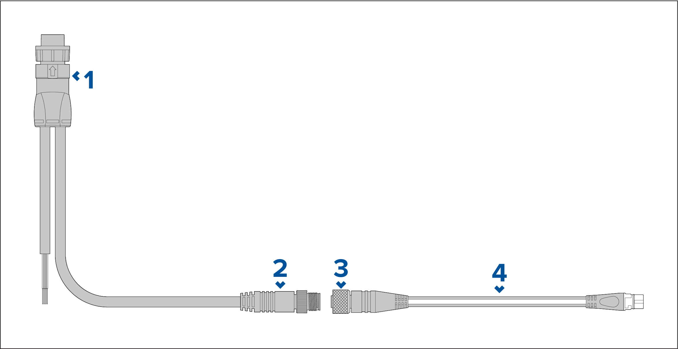
- Power/NMEA 2000 cable connects to the rear of the MFD.
- DeviceNet (Micro-C 5 pin male) connector connects to NMEA 2000 network or SeaTalkng ® via adaptor cable.
- DeviceNet (5 pin female) connector.
-
Adaptor cable connects to SeaTalkng
®
backbone or DeviceNet spur cable connects to NMEA 2000 network.
Available cables
- A06045 — Female DeviceNet to SeaTalkng ® cable, shown.
- E05026 — Female DeviceNet to bare end wires.
Note:
|
Transducer connection
Note:
|
RealVision ™ 3D transducer extension cable
DownVision ™ transducer extension cable
- A 4 m (13.1 ft.) Transducer extension cable (A80273) is available.
- It is recommended that only one cable extension is used.
Axiom transducer adaptor cables
Axiom DV adaptor cables
| A80484 |
Axiom DV to 7-pin Embedded Transducer Adapter |
| A80485 |
Axiom DV to 7-pin CP370 Transducer Adapter |
| A80486 |
Axiom DV to 9-pin DV & 7-Pin Embedded Transducers Y-Cable |
| A80487 |
Axiom DV to 9-pin DV & 7-Pin CP370 Transducers Y-Cable |
Axiom RV adaptor cables
| A80488 |
Axiom RV to 7-pin Embedded Transducer Adapter |
| A80489 |
Axiom RV to 7-pin CP370 Transducer Adapter |
| A80490 |
Axiom RV to 9-pin DV Transducer Adapter |
| A80491 |
Axiom RV to 25-pin RV & 7-pin Embedded Transducers Y-Cable |
| A80492 |
Axiom RV to 25-pin RV & 7-pin CP370 Transducers Y-Cable |
| A80493 |
Axiom RV to 7-pin Embedded & 9-pin DV Transducers Y-Cable |
| A80494 |
Axiom RV to 7-pin CP370 & 9-pin DV Transducers Y-Cable |
Caution: Transducer cable |
|
Network connection
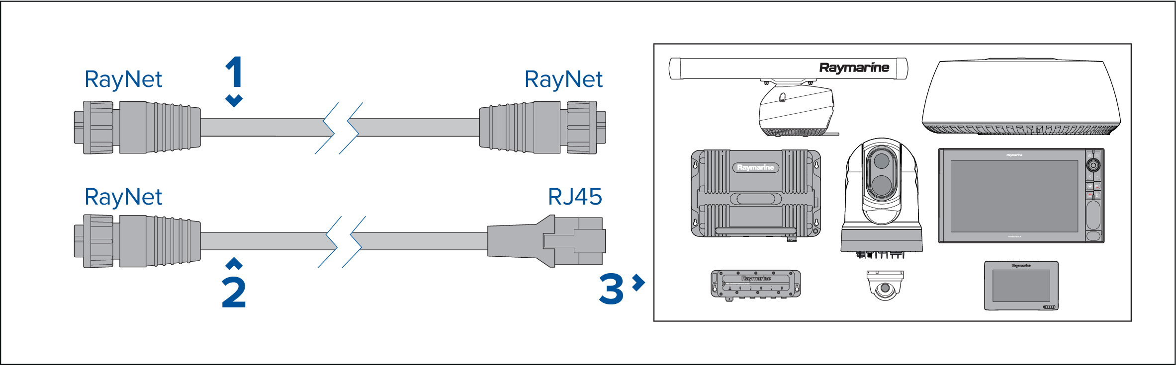
- RayNet to RayNet cable — Connect one end of the RayNet cable to your MFD and the opposite end to a RayNet device or RayNet network switch.
- RayNet to RJ45 cable — Connect the RayNet end of the cable to your MFD and the opposite end to an RJ45 device or RJ45 network switch or coupler.
- Compatible network devices, such as a Network switch, Radar scanner, Sonar module, Thermal camera etc.
Note:
|
Accessory connection
The following functions require a card reader attached to the MFD:
- use of electronic cartography — alternatively cartography can be shared from a networked MFD that does have a card reader attached.
- updating product software — alternatively if your MFD has a connection to the internet you can check online for software updates.
- import and export user data (waypoints, routes and tracks) — alternatively user data can be imported and exported from a networked MFD that does have a card reader attached.
- backup and restore settings — alternatively settings can be backed up and restored from a networked MFD that does have a card reader attached.
- viewing pdf files
- (1) capturing and viewing screenshots or images (.png, .jpg files)
- (2) recording and viewing video files (.mov files )
- installation of third-party LightHouse app (.apk files) (for installation only; apps cannot be run directly from storage device).
Important:
|
In addition to the storage uses listed above, the USB slot on the RCR-SDUSB can also supply 0.5A of current to charge mobile devices.
|
Device |
Supported media |
|---|---|
|
RCR-SDUSB (A80440)) |
1x SD card (or MicroSD card when using an SD card adaptor) 1x USB (Type A connector) (e.g. for connection of an external USB hard drive or pen / flash drive) |
|
RCR-2 (A80218)) |
2x MicroSD card |
For installation details for these devices, please refer to the instructions provided with your accessory.
|
|
Warning: USB device power |
|
Do NOT connect any device to the product’s USB connection that requires an external power source. |
Maintaining your display
Caution: Product cleaning |
|
When cleaning products:
|
Troubleshooting
Troubleshooting
The troubleshooting information provides possible causes and corrective action required for common problems associated with installation and operation of your product.
Before packing and shipping, all Raymarine products are subjected to comprehensive testing and quality assurance programs. If you do experience problems with your product this section will help you to diagnose and correct problems in order to restore normal operation.
If after referring to this section you are still having problems with your product, please refer to the Technical support section of this manual for useful links and Raymarine Product Support contact details.
LED Diagnostics
Normal states
| MFD status | LED color | LED state |
|---|---|---|
|
On |
White |
On (Brightness increases with display brightness) |
|
Off |
Red |
On |
|
Recovery |
Blue |
On |
Error states
| Fault | LED color | LED state |
|---|---|---|
|
Low voltage |
Red |
Slow flash — one flash per second |
|
High voltage |
Red |
Fast flash — two flashes per second |
|
High temperature |
Red and Blue |
Alternating |
Power up troubleshooting
Product does not turn on or keeps turning off
| Possible causes | Possible solutions |
|---|---|
|
Blown fuse / tripped breaker. |
|
|
Poor / damaged / insecure power supply cable / connections |
|
|
Incorrect power connection |
The power supply may be wired incorrectly, ensure the installation instructions have been followed. |
Product will not start up (restart loop)
| Possible causes | Possible solutions |
|---|---|
|
Power supply and connection |
See possible solutions from the table above, entitled ‘Product does not turn on or keeps turning off’. |
|
Software corruption |
|
Performing a power on reset — Axiom ™
Important:
|
GNSS (GPS) troubleshooting
| Problem | Possible causes | Possible solutions | |
|---|---|---|---|
| “No Fix” GNSS status icon is displayed. | Geographic location or prevailing conditions preventing satellite fix. | Check periodically to see if a fix is obtained in better conditions or another geographic location. | |
| GNSS (GPS) connection fault. | Ensure that external GNSS connections and cabling are correct and fault free. | ||
| External GNSS (GPS) receiver in poor location.
For example:
|
Ensure GNSS (GPS) receiver has a clear view of the sky. |
||
|
GNSS (GPS) installation problem. |
Refer to the installation instructions. |
||
|
|||
Sonar troubleshooting
Scrolling image is not being displayed
| Possible causes | Possible solutions |
|---|---|
| Sonar disabled |
Select Ping Enable from the Sonar app’s Sounder menu. |
| Incorrect transducer selected |
Check that the correct transducer is selected in the Sonar app’s Transducer menu. |
| Damaged cables |
|
| Damaged or fouled transducer |
Check the condition of the transducer ensuring it is not damaged and is free from debris/fouling, clean or replace as necessary. |
| Wrong transducer fitted |
Ensure the transducer is compatible with your system. |
| External sonar module: SeaTalkhs ™ / RayNet network problem. |
|
| External sonar module: Software mismatch between equipment may prevent communication. | Ensure all Raymarine products contain the latest available software, check the Raymarine website: www.raymarine.com/software for software compatibility. |
No depth reading / lost bottom lock
| Possible causes | Possible solutions |
|---|---|
| Transducer location |
Check that the transducer has been installed in accordance with the instructions provided with the transducer. |
| Transducer angle |
If the transducer angle is too great the beam can miss the bottom, adjust transducer angle and recheck. |
| Transducer kicked-up |
If the transducer has a kick-up mechanism, check that it has not kicked up due to hitting an object. |
| Power source insufficient |
With the product under load, using a multi-meter, check the power supply voltage as close to the unit as possible to establish actual voltage when the current is flowing. (Check your product’s Technical specification for power supply requirements.) |
| Damaged or fouled transducer |
Check the condition of the transducer ensuring it is not damaged and is free from debris / fouling. |
| Damaged cables |
|
| Vessel speed too high |
Slow vessel speed and recheck. |
| Bottom too shallow or too deep |
The bottom depth may be outside of the transducers depth range, move vessel to shallower or deeper waters as relevant and recheck. |
Poor / problematic image
| Possible causes | Possible solutions |
|---|---|
| Vessel stationary |
Fish arches are not displayed if the vessel is stationary; fish will appear on the display as straight lines. |
| Scrolling paused or speed set too low |
Unpause or increase sonar scrolling speed. |
| Sensitivity settings may be inappropriate for present conditions. |
Check and adjust sensitivity settings or perform a Sonar reset. |
| Damaged cables |
|
| Transducer location |
|
| Transducer kicked-up |
If the transducer has a kick-up mechanism, check that it has not kicked up due to hitting an object. |
| Damaged or fouled transducer |
Check the condition of the transducer ensuring it is not damaged and is free from debris / fouling. |
| Damaged transducer cable |
Check that the transducer cable and connection is free from damage and that the connections are secure and free from corrosion. |
| Turbulence around the transducer at higher speeds may affect transducer performance |
Slow vessel speed and recheck. |
| Interference from another transducer |
|
| Unit power supply fault |
Check the voltage from the power supply, if this is too low it can affect the transmitting power of the unit. |
Wi-Fi troubleshooting
Cannot find network
| Possible cause | Possible solutions |
|---|---|
| Wi-Fi not currently enabled on devices. | Ensure Wi-Fi is enabled on both Wi-Fi devices and rescan available networks. |
| Some devices may automatically turn off Wi-Fi when not in use to save power. | Power cycle / reboot devices and rescan available networks. |
| Device not broadcasting. |
|
| Devices out of range or signal being blocked. | Move devices closer together or, if possible remove the obstructions and then rescan available network. |
Cannot connect to network
| Possible cause | Possible solutions |
|---|---|
| Some devices may automatically turn off Wi-Fi when not in use to save power. | Power cycle/reboot devices and retry the connection. |
| Trying to connect to the wrong Wi-Fi network | Ensure you are trying to connect to the correct Wi-Fi network, the Wi-Fi network’s name can be found in the Wi-Fi settings on the broadcasting device (the device that you are trying to connect to). |
| Incorrect network credentials | Ensure you are using the correct passphrase, the Wi-Fi network’s passphrase can be found in the Wi-Fi settings on the broadcasting device (the device that you are trying to connect to). |
| Bulkheads, decks and other heavy structure can degrade and even block the Wi-Fi signal. Depending on the thickness and material used it may not always be possible to pass a Wi-Fi signal through certain structures |
|
| Interference being caused by other Wi-Fi enabled or older Bluetooth enabled devices (Bluetooth and Wi-Fi both operate in the 2.4 GHz frequency range, some older bluetooth devices may interfere with Wi-Fi signals.) |
|
Interference caused by other devices that use the 2.4GHz frequency See list below of some common devices that use the 2.4GHz
frequency:
|
Temporarily switch off each device in turn until you have identified the device causing the interference, then remove or reposition the offending device(s). |
| Interference caused by electrical and electronic devices and associated cabling could generate an electromagnetic field which may interfere with the Wi-Fi signal. | Temporarily switch off each item in turn until you have identified the device causing the interference, then remove or reposition the offending device(s). |
Connection extremely slow and or keeps dropping out
| Possible cause | Possible solutions |
|---|---|
| Wi-Fi performance degrades over distance so products farther away will receive less network bandwidth. Products installed close to their maximum Wi-Fi range will experience slow connection speeds, signal drop outs or not being able to connect at all. |
|
| Interference being caused by other Wi-Fi enabled or older Bluetooth enabled devices (Bluetooth and Wi-Fi both operate in the 2.4 GHz frequency range, some older bluetooth devices may interfere with Wi-Fi signals.) |
|
| Interference from devices on other vessels. When in close proximity to other vessels, for example, when moored up in a marina, many other Wi-Fi signals may be present. |
|
Network connection established but no data
| Possible cause | Possible solutions |
|---|---|
| Connected to the wrong network. | Ensure that your devices is connected to the correct network. |
| Device software incompatibility | Ensure both devices are running the latest available software. |
| It may be possible that the device has become defective |
|
Mobile application running slowly or not at all
| Possible cause | Possible solutions |
|---|---|
| Raymarine app not installed | Install mobile app from relevant app store. |
| Raymarine app version not compatible with MFD software | Ensure mobile app and MFD software are latest available versions. |
| Mobile apps not enabled on MFD | Enable “Viewing only” or “Remote Control” as required in the Mobile Apps setting on your MFD. |
Touchscreen troubleshooting
| Problem | Possible causes | Possible solutions |
|---|---|---|
| Touchscreen does not operate as expected. | TouchLock is enabled. | Swipe your finger from left to right across the Power button swipe area to de-activate the TouchLock. |
| Screen is not being operated with bare fingers, for example gloves are being worn. | Bare fingers must make contact with the screen for correct operation. Alternatively you may use conductive gloves. | |
| Water deposits on the screen. | Carefully clean and dry the screen in accordance with the instructions provided. |
Miscellaneous troubleshooting
| Problem | Possible causes | Possible solutions |
|---|---|---|
Display behaves erratically:
|
Intermittent problem with power to the display. | Check relevant fuses and breakers. |
| Check that the power supply cable is sound and that all connections are tight and free from corrosion. | ||
| Check that the power source is of the correct voltage and sufficient current. | ||
| Software mismatch on system (upgrade required). | Go to www.raymarine.com and click on support for the latest software downloads. | |
| Corrupt data / other unknown issue. | Perform a factory reset.
|
Technical support
Raymarine product support and servicing
Product information
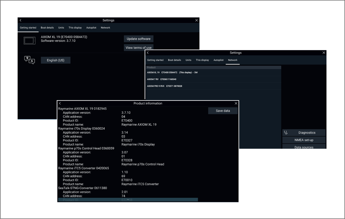
If you need to request service or support, please have the following information to hand:
- Product name.
- Product identity.
- Serial number.
- Software application version.
- System diagrams.
You can obtain this product information using diagnostic pages of the connected MFD.
Servicing and warranty
Raymarine offers dedicated service departments for warranty, service, and repairs.
Don’t forget to visit the Raymarine website to register your product for extended warranty benefits: http://www.raymarine.co.uk/display/?id=788.
| Region | Contact |
|---|---|
|
United Kingdom (UK), EMEA, and Asia Pacific |
|
|
United States (US) |
|
Web support
Please visit the “Support” area of the Raymarine website for:
- Manuals and Documents — http://www.raymarine.com/manuals
- Technical support forum — http://forum.raymarine.com
- Software updates — http://www.raymarine.com/software
Worldwide support
| Region | Contact |
|---|---|
|
United Kingdom (UK), EMEA, and Asia Pacific |
|
|
United States (US) |
|
|
Australia and New Zealand (Raymarine subsidiary) |
|
|
France (Raymarine subsidiary) |
|
|
Germany (Raymarine subsidiary) |
|
|
Italy (Raymarine subsidiary) |
|
|
Spain (Authorized Raymarine distributor) |
|
|
Netherlands (Raymarine subsidiary) |
|
|
Sweden (Raymarine subsidiary) |
|
|
Finland (Raymarine subsidiary) |
|
|
Norway (Raymarine subsidiary) |
|
|
Denmark (Raymarine subsidiary) |
|
|
Russia (Authorized Raymarine distributor) |
|
Viewing product information (LightHouse ™ 3)
The Getting started menu contains hardware and software information for your MFD.
Learning resources
Video tutorials


Note:
|
Training courses
Raymarine regularly runs a range of in-depth training courses to help you make the most of your products. Visit the Training section of the Raymarine website for more information:
Technical specification
Axiom tech spec
Power
|
Axiom ™ 7 |
Axiom ™ 9 |
Axiom ™ 12 |
|
|---|---|---|---|
|
Nominal supply voltage: |
12 V dc |
||
|
Operating voltage range: |
8 V dc to 16 V dc |
||
|
Fuse requirements: |
|
||
|
Power consumption: (Maximum @ 12 V dc) |
|
|
|
|
Note:
Power consumption figures for DV variants were taken using a CPT-100DVS transducer and RV variants using a RV-100 transducer. |
Environmental
|
Axiom ™ 7 |
Axiom ™ 9 |
Axiom ™ 12 |
|
|---|---|---|---|
|
Operating temperature range: |
-25°C to + 55°C |
||
|
Storage temperature range: |
-30°C to + 70°C |
||
|
Humidity: |
up to 93% @ 40°C |
||
|
Water ingress protection: |
IPx6 and IPx7 |
||
LCD specification
|
Axiom ™ 7 |
Axiom ™ 9 |
Axiom ™ 12 |
|
|---|---|---|---|
|
Size (diagonal): |
7.0” |
9.0” |
12.1” |
|
Type: |
TN (Twisted Nematic) |
IPS (In-Plane Switching) |
|
|
Color depth: |
24 bit |
||
|
Resolution: |
WVGA 800 x 480 |
WXGA 1280 x 800 |
|
|
Ratio: |
5:3 |
16:10 |
|
|
Illumination: |
1200 nits / 1200 cd/m2 |
||
|
Viewing angle: |
Top 60 / Bottom 70 / Left 70 / Right 70 |
Top 88 / Bottom 88 / Left 88 / Right 88 |
|
|
Number of simultaneous touches: |
2 |
1 to 16 |
|
Data connections
|
Axiom ™ 7 |
Axiom ™ 9 |
Axiom ™ 12 |
|
|---|---|---|---|
|
Transducer: |
|
25 pin RealVision ™ type connector |
|
|
NMEA 2000: |
1 x DeviceNet (male connector built into power cable.) |
||
|
Accessory connection: |
1 x USB Micro B |
||
|
Network: |
1 x RayNet type SeaTalkhs ™ connector (10/100 Mbits/s) |
||
|
Wi-Fi: |
1 x 802.11/b/g/n |
||
|
Bluetooth: |
1 x Bluetooth V4.0 |
||
|
LEN (Load Equivalency Number): |
1 |
||
Storage
|
Axiom ™ 7 |
Axiom ™ 9 |
Axiom ™ 12 |
|
|---|---|---|---|
|
Internal: |
4GB Solid State (2 GB usable) |
||
|
External microSD card: |
1 x MicroSDXC card slot |
||
|
External (via RCR-SDUSB accessory): |
|
||
|
External (via RCR-2 accessory) |
2 x MicroSDHC card slots |
||
Internal sonar specification
DownVision ™ sonar specification
| Channels | 2 channels
|
| Beam coverage |
|
| Range |
|
RealVision ™ 3D sonar specification
Internal GNSS (GPS / GLONASS) receiver specification
| Channels | Multiple — ability to simultaneously track up to 28 satellites |
| Cold start | <2 minutes |
| Receiver IC Sensitivity |
|
| GNSS compatibility |
|
| SBAS compatibility |
|
| Operating frequency | 1574 MHz to 1605 MHz |
| Signal Acquisition | Automatic |
| Almanac Update | Automatic |
| Geodetic Datum | WGS-84 (alternatives can be selected on the MFD) |
| Refresh Rate | 10 Hz (10 times per second) |
| Antenna |
|
| Position Accuracy |
|
| Note: * Supported in future software update. |
Spares and accessories
AXIOM accessories
| Part number | Name | Details |
|---|---|---|
| A80440 | RCR-SDUSB | External MicroSD and USB reader |
| A80515 | Right angled RV transducer adaptor cable | |
| A80498 | 7” Front installation kit | Includes:
|
| A80499 | 7” Front mount suncover | |
| A80500 | 9” Front installation kit | Includes:
|
| A80501 | 9” Front mount suncover | |
| A80502 | 12” Front installation kit | Includes:
|
| A80503 | 12” Front mount suncover |
Axiom transducer adaptor cables
Axiom DV adaptor cables
| A80484 |
Axiom DV to 7-pin Embedded Transducer Adapter |
| A80485 |
Axiom DV to 7-pin CP370 Transducer Adapter |
| A80486 |
Axiom DV to 9-pin DV & 7-Pin Embedded Transducers Y-Cable |
| A80487 |
Axiom DV to 9-pin DV & 7-Pin CP370 Transducers Y-Cable |
Axiom RV adaptor cables
| A80488 |
Axiom RV to 7-pin Embedded Transducer Adapter |
| A80489 |
Axiom RV to 7-pin CP370 Transducer Adapter |
| A80490 |
Axiom RV to 9-pin DV Transducer Adapter |
| A80491 |
Axiom RV to 25-pin RV & 7-pin Embedded Transducers Y-Cable |
| A80492 |
Axiom RV to 25-pin RV & 7-pin CP370 Transducers Y-Cable |
| A80493 |
Axiom RV to 7-pin Embedded & 9-pin DV Transducers Y-Cable |
| A80494 |
Axiom RV to 7-pin CP370 & 9-pin DV Transducers Y-Cable |
Legacy MFD adaptor plates
| Existing legacy MFD | Adaptor part number | New MFD | Fixing holes |
|---|---|---|---|
| a9x | A80526 | Axiom 9” | Existing |
| a12x | A80527 | Axiom 12” | New |
| c12x / e12x | A80528 | Axiom 12” | Existing |
| C70 Classic | A80525 | Axiom 9” | New |
| C80 / E80 Classic | A80564 | Axiom 9” | Existing |
| C120 / E120 Classic | A80529 | Axiom 12” | Existing |
| e7 / e7D | A80524 | Axiom 7” | Existing |
|
Note:
The adaptor plates have been designed to utilize your legacy MFD’s existing cut out and fixing holes. Where it is not possible to reuse existing fixing holes then a mounting template is supplied, which provides the location for the new fixing holes. |
AXIOM spares
| Part number | Name | Details |
|---|---|---|
| R70523 | Power/DeviceNet combined cable 1.5m (4.92 ft) | |
| R70561 | Right angled Power/DeviceNet combined cable 1.5m (4.92 ft) | |
| R70525 | 7” Trunnion mount suncover | |
| R70526 | 7” Rear cover | For trunnion and rear installation |
| R70527 | 7” Surface mount suncover | |
| R70528 | 7” Rear mounting kit | Includes 2 x metal brackets, 4 x studs and 4 x thumb nuts |
| R70524 | 7” Metal trunnion mounting kit | Includes trunnion and 2 knobs |
| R70529 | 9” Metal trunnion mounting kit | Includes trunnion and 2 knobs |
| R70530 | 9” Trunnion mount suncover | |
| R70531 | 9” Rear mounting kit | Includes 2 x metal brackets, 4 x studs and 4 x thumb nuts |
| R70532 | 12” Metal trunnion mounting kit | Includes trunnion and 2 knobs |
| R70533 | 12” Trunnion mount suncover | |
| R70534 | 12” Rear mounting kit | Includes 2 x metal brackets, 4 x studs and 4 x thumb nuts |
RayNet to RayNet cables and connectors
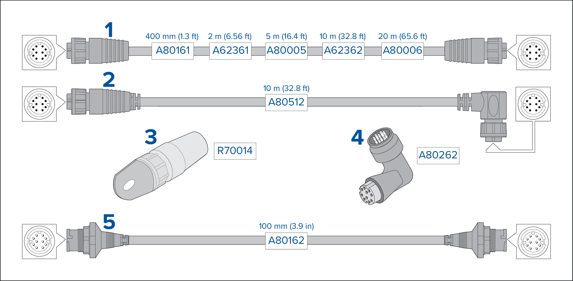
| Description | |
|---|---|
| 1 |
Standard RayNet connection cable with a RayNet (female) socket on both ends. |
| 2 |
Right-angle RayNet connection cable with a straight RayNet (female) socket on one end, and a right-angle RayNet (female) socket on the other end. Suitable for connecting at 90° (right angle) to a device, for installations where space is limited. |
| 3 |
RayNet cable puller (5 pack). |
| 4 |
RayNet to RayNet right-angle coupler / adapter. Suitable for connecting RayNet cables at 90° (right angle) to devices, for installations where space is limited. |
| 5 |
Adapter cable with a RayNet (male) plug on both ends. Suitable for joining (female) RayNet cables together for longer cable runs. |
RayNet to RJ45 adapter cables
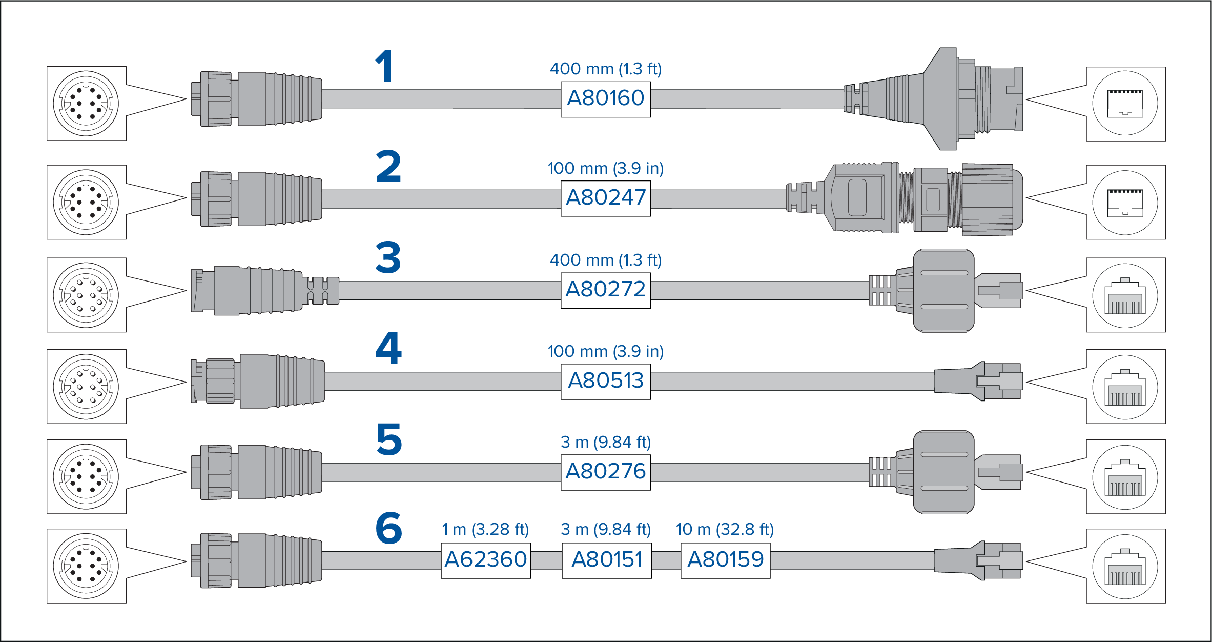
| Description | |
|---|---|
| 1 | Adapter cable with a RayNet (female) socket on one end, and a waterproof (female) socket on the other end accepting the following cables with an RJ45
SeaTalkhs
waterproof locking (male) plug:
|
| 2 | Adapter cable with a RayNet (female) socket on one end, and a waterproof (female) RJ45 socket on the other end, along with a locking gland for a watertight fit. |
| 3 | Adapter cable with a RayNet (male) plug on one end, and an RJ45 SeaTalkhs waterproof (male) plug on the other end. |
| 4 | Adapter cable with a RayNet (male) plug on one end, and an RJ45 SeaTalkhs (male) plug on the other end. |
| 5 | Adapter cable with a RayNet (female) socket on one end, and an RJ45 SeaTalkhs waterproof (male) plug on the other end. |
| 6 | Adapter cable with a RayNet (female) socket on one end, and an RJ45 SeaTalkhs (male) socket on the other end. |
SeaTalkng ® cables and accessories